Please
'Boom' Responsibly As
most of you have noticed, the noise ordinances have
become much tougher lately. Most of this is due to
idiots, yes IDIOTS, who drive through residential areas
with their windows down while their system is playing at
full power. To make things worse, the music they listen
to has all sorts of foul language that's not suitable for
small children, (who may be playing outside). There are
even a few people, who are even beyond idiot status, that
play their systems at full power through residential
areas after 10:00 PM (when many people go to bed). I
don't believe that this type of behavior is good for the
industry. If the fines get too stiff, people will stop
buying large systems. If this happens, more people will
get out of car audio (who wants a mediocre system).
People get interested in things because they're exciting.
A deck and four 6.5" speakers are not going to
interest many of the younger car audio enthusiasts. If
car audio enthusiasts keep annoying more and more people,
the fines will keep getting tougher. All of this will
only reduce interest in the equipment that fuels the
industry. If you want to listen to your system at full
volume, get out on the highway where there's little
chance of bothering anyone. When you get to a red light,
turn it down. If the only thing attractive about you is
your 'system', you have some work to do. Bottom line...
Think about what you're doing. Think about other people.
It's not the end of the world if you have to turn the
volume down for a little while.
Car Stereo Installation Primer
This page is
simply a very basic primer on what's required for basic
installations. It will not be a step by step installation
manual. It will describe some basic upgrades and tell you
basically what's involved with equipment and labor. Since
this is at the beginning of the directory and some of the
terms have not yet been covered, there will be links to
pages with more detail about each new term. Hopefully,
this page will help you to make more educated decisions
when you buy and install your equipment.
Making
Good Decisions: Before you
can choose the right audio components, you need to decide
on what you want from your audio system. Some just want
to upgrade from an old stock stereo cassette deck to a CD playerhead unit.
Others will want a full blown competition system. Some
want quality. Others want quantity.
If you only want to buy your equipment once and be done
with it, think about what you want. A lot of people buy
equipment without any forethought and are dissatisfied
with the results.
Many people are on a budget but
still want to upgrade their sound system. By_far, the
speakers are the most critical, variable component. For
the most part, amplifiers and head units sound relatively
similar among the better brands (Pioneer, Alpine and
Kenwood...). Speakers, on the other hand, are very
different from brand to brand (or even between the
different product lines from the same manufacturer).
There are a lot of cheap/inexpensive speakers out there.
Many sound really bad (note: if
you're looking for quality sound, the 'loudest' speaker
isn't necessarily the 'best' speaker). Some are pretty
decent. If you're on a budget (it's
less critical if you're spending $300-$400 on a pair of
high end component speakers like those from Quart, Morel
or Focal), the trick is to go listen to the speakers with
a well recorded CD (preferably one that you like). Visit
as many stores as possible. In each store, find a low end
(inexpensive) high quality deck (Alpine, Pioneer,
Kenwood...) and set all of the tone controls to flat
(zero). Turn off any DSP such (ambience, theater, hall
effect...). Also turn off any other equalization (BBE,
parametrics...). This will give you a chance to listen to
all of the speakers with essentially the same signal. If
possible, listen to all of the speakers using the head
unit's internal amplifier (this will assure you that
you're listening to the same power output in all cases -
~20 watts per channel no matter the power rating on the
deck). Listen to the speakers to see if there are any
peaks in the frequency response (the peaks will cause
certain parts of the audio spectrum to be annoying). If
there are, go to the next set of speakers (peaks that are
easily noticed will be hard to get rid of - even with a
good equalizer). Find a set of speakers that have good
full range sound without any annoying peaks and no
significant dips in their frequency response. If you need
to, bring a note pad to write down the model number and
brand of speakers and any likes or dislikes.
If you've never heard good frequency
response, find a high end home stereo demo room (there
may be one in the same store). They will be able to play
your CD through home speakers. Good quality home speakers
will have a good flat frequency response. Look for brands
like Polk, Infinity, Paradigm. Listen to speakers
'without' internal amplification (such as those with
built-in powered subwoofers) and with woofers no larger
than ~8". Speakers with dual 6" woofers are
often a good choice. Again, tell them to set all of the
equalization/tone/processing to flat or off (using an
amplifier that doesn't have any digital processing and
actual knobs for bass and treble will help assure that
you're listening to a 'clean' signal). Listen to your
favorite song on the CD a few times to help you remember
what it sounds like. Notice the relative level of
individual instruments (compared to the other instruments
and the vocals).
Oh, yeah... Don't forget to take
your CD when you leave each store. :)
OEM System Upgrades
OEM
Systems: Most all vehicles
come from the factory with a stereo system. The least
expensive have an AM/FM radio (no cassette or CD) and 2 speakers. Most will have a cassette player and 4
speakers. Since most head units drive the speakers
directly (no external power amplifiers) they have to have internal power
amplifiers. These amplifier are limited in power and may not provide enough power for some.
For those that don't know, OEM stands for Original
Equipment Manufacturer. It simply means that the radio
was supplied by the manufacturer of the vehicle.
OEM
Systems with External Power Amplifiers: There are quite a few manufacturers that
have high end audio systems that use external amplifiers.
Sometimes there's only one external amplifier which is
used to power an OEM subwoofer. Many times, this
amplifier is mounted under the rear deck. If the system
uses external amplifiers for all of the speakers, the
amplifiers are mounted under the seat, in the doors or in
the trunk. Sometimes, the external amplifiers are needed
because there was no room in the head unit for
amplifiers. Other times it's so that they can provide
more power to the speakers than you can get with an
internal amplifier. This was the case with the Bose® systems. They used switching (class D)
amplifiers and low impedance speaker to provide as much
as 80 watts (of RMS power) per channel to the speakers.
If you're upgrading the speakers with this type of
system, many times, it's much more expensive than with
other systems. Since the amplifiers are designed to work
exclusively with the low impedance speakers, they will
not work well with the new speakers. Even if you do use
the stock amplifiers, the output may be significantly
less due to the higher impedance of the new speakers.
When upgrading from this type of system and you want to
retain the stock head unit, you'll generally need a
special adapter to get a useable preamp level signal from
the head unit. You'll need an amplifier with enough
output channels to drive all of your speakers and you'll
need new speakers. The following companies can provide
information and interface products for virtually all OEM
systems.
Basic
Requirements: If you have no
audio equipment in your vehicle, you'll need (at least) a
head unit and a pair of speakers. Virtually all
aftermarket head units have internal amplifiers. The
exceptions are generally the top_of_the_line models. If
you plan on upgrading to a system in the future, you'll
want a head unit with at least one pair of preamp level
(RCA) outputs.
Features: Most people want certain features on their
head units and that, along with cost, will determine the
head unit that they buy. There are a few things that I
will recommend.
No motorized face. They have
significantly more problems than rigid faced
units. Even flip down faces have more problems
than the rigid faced units. If you have to have a
deck with a motorized face, get an extended
warranty.
Remote controls... Many think a
remote is for those who are too lazy to reach for
the radio. A remote control has a few significant
advantages. They are safer because you can make
changes without having to take your eyes off of
the road. They also reduce the wear and tear on
your head unit. Most head units have very small
(sometimes cheaply made) switches for volume,
track, station preset and such. If you repeatedly
push these buttons with more force than
necessary, they will fail. Some fail within a
year. Replacing these small switches can be
expensive. Using the remote allows these switches
to last much longer and also allows the face
plate around the buttons to remain as new. If the
switches in the remote wear out, the remote can
be replaced for less than the cost to repair the
face of the head unit.
RF
Modulators: When adding
certain accessories like a CD changer or an MP3 player or
a satellite radio receiver to an OEM system (or any
system without an auxiliary input), you need some way to
get the signal into the audio system. Since very few head
units have auxiliary signal inputs, there's generally no
direct preamp signal level input path. That's where the
RF Modulator comes into play. The RF (radio frequency)
modulator is essentially a micropower radio station. It
basically takes an audio signal and mixes it with a radio
frequency signal. This allows the signal to pass through
the tuner (where the RF part of the signal is stripped
from the audio signal) and into the audio stream. You
tune your radio to one of two (or more) selectable
channels (the frequencies are determined by the designer
of the RF modulator) to hear the signal. It's not quite
as good as having a direct preamp level input signal path
but it's generally pretty good. Crutchfield
generally has a few different models from which to
choose.
RF
Modulated Changers: Some CD
changers are designed to be used with RF modulators (some
work 'only' with modulators). For these changers, you'll
generally have a small display that mounts on or near the
dash. The controller is generally connected to the
changer by a special multi-conductor cable that has to be
run from the changer to the controller.
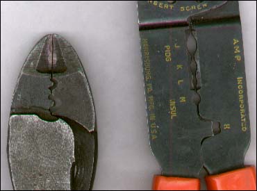
Tools
Crimping
Tools: Below you see 2
different styles of crimping tools. They are different in
several ways. The one on the left is a very heavy duty
pair made by Thomas and Betts. As you can see, the end is
made for cutting (and stripping). The section closer to
the pivot is made for crimping. In this case, these are
made for crimping UNinsulated
terminals. They will work for insulated connectors but
they generally destroy the insulator. The pair on the
right is a somewhat less robust type of crimping tool
(although this pair has performed better than most of
this type). You can see that there are 3 oval shaped
spaces in the middle of the tool. These are for crimping
insulated terminals. The best type of crimper for car
audio work is one that is built like the tool on the left
but is designed to crimp insulated terminals. To strip
with the T&B type crimpers, you simply apply enough
pressure to cut through the insulation and then (with the
jaws still clamped on the wire) pull the insulation off
of the end of the wire. If the insulation is tough, cut
through the insulation, turn the wire 90° and cut
through the insulation again. Then pull the insulation
off of the wire. For tough insulation, wrap the wire
around your hand (to prevent it from slipping through
your hand) and use you thumb as a fulcrum to help pull
the insulation off. Expect to pay between $20 and $30 for
a good pair of hand crimpers. For very large wire, there
are different types of crimpers. Some are used with a
hammer to crimp the terminals onto the wire. Others are
ratchet type crimpers that allow you to have significant
leverage to make the crimp. Many of the ratchet crimpers
assure perfect crimping because they have to crimp to a
precise thickness to complete the cycle and remove the
crimp connector from the tool.
Connectors
There are many types of connectors
that can be used for car audio. I'll cover just a few
here.
Butt
Splice Connectors: The most
common connector is the butt splice connector. It is
generally a copper tube covered with a PVC insulator. As
you can see in the photo below, the butt connector has a
bell on each end. This makes it easier to insert the
wire. The point where the bell tapers is where the actual
copper conductor/connector begins on the inside. The
black outline shows the approximate size of the copper
tube inside the insulator. The middle of the tube has a
'stop' to prevent inserting the wire too far. The other
end of the white wire is stripped the right amount. The
amount of bare wire isn't real critical but it should
ideally go to the center stop point and not allow any of
the copper to show at the point where it enters the
connector. You'll notice that the insulator is RED. This
indicates that it is designed to accept a certain range
of wire sizes. Red connectors are designed to accept
wires between 22g and 18g. Blue connectors are for wire
sizes 14g to 16g. Yellow connectors are for 12g to 10g.
For larger wire sizes, the colors start over again but
the difference in size is so significant that you'll
never be confused on which wire a given color connector
is to be used.
Closed
End Crimp Caps: Many
installers use closed end connectors with good results.
For this type of connector, you strip the wires, twist
them together, place the cap over the twisted wire and
crimp it. They're especially good when you need to
connect more than 2 wires. They may be better (less
likely to pull apart) than butt connectors for newbies.
The biggest problem I find is that it's not as easy to
make a nice, neat wiring harness with them. Other than
that, they work fine. In the drawing, the cap has already
been crimped. The dashed lines show the uncrimped
dimensions.
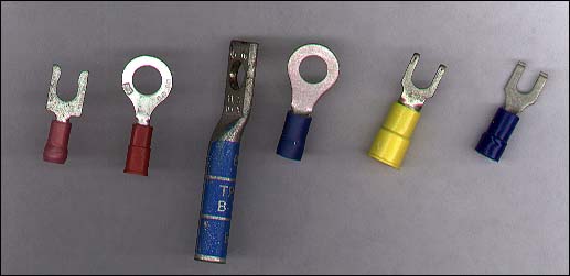
Spade
and Ring Terminals: Below is
an assortment of ring and spade terminals. The 2 on the
left are for use with wire gauges between 18 and 22. The
left-most terminal is a spade terminal designed to hold
the terminal block's screw so that it doesn't slip out
when tightening the screw on the terminal block. These
are good for when you're working in tight spaces. As you
can see, the other red terminal is a ring terminal. The
large ring terminal is used for 6g wire. As I said above,
the colors repeat. Even so, you're not likely to get it
confused with terminals designed for 14-16g wires (like
the one just to it's right). The yellow terminal is a
standard spade terminal that's designed to work with
12-10g wires. The right-most blue terminal is also a
spade terminal but has the tips of its forks bent up at a
right angle (kind of hard to see). This prevents if from
pulling out from under a screw if something pulls on the
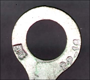
wire. All of these terminals have at least 2 important
specs. The wire size with which it is to be used and the
screw or stud size that it can accommodate. The second
image shows how the terminals are sometimes marked to
show wire size.
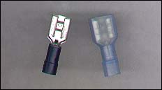
Push-on
Terminals: This type of
terminal is used on most speakers. In the Photo below,
you can see that one is fully insulated and one in
uninsulated. If you were using them in-line (one female
push-on and one male push-on - both on the ends of
wires), the fully insulated would be the best choice. For
speakers, the uninsulated terminal is often preferred
because it allows you to push it farther onto the
speaker's terminal (the insulator doesn't get in the
way).
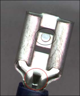
In the image below, you can see a
push-on terminal and 2 circles/ovals. The black oval
highlights a small protrusion. It's purpose is to lock
the terminal onto the male counterpart. You've probably
noticed that there's almost always a slot in the middle
of the speaker terminal. It's there for this lock to fall
into. The red oval highlights the wire stop. It simply
prevents the wire from going too far and possibly
preventing the terminal from fully sliding onto the
speaker terminal.
Wire
Nuts: Many people use wire
nuts when installing their stereos simply because they're
available. For most all situations, wire nuts are not a
good idea for car audio. When used for household wiring,
they're used to connect 2 or 3 single stranded wires in a
vibration free environment. This is much different than
in a vehicle. Wire nuts don't hold well on finely
stranded wire and will eventually work loose. The photo
below shows the inside of a wire nut. This one has 2
threaded sections. The bottom is plastic and is designed
to grab onto the insulation. The top has a metal
wirewound insert that grabs onto the copper. If you were
going to wire your house, this would be a good choice.
For a car, it's a bad choice.
Scotch-Loks
and T-taps: The next 3
images are of a 'Scotch lok' type in-line tap connector.
Scotch Loks are used where you need to tap into a wire
but don't want to have to cut it. They are most commonly
used in situations like splicing in a boat trailer
connector. You can tap into the brake and running lights
without having to cut the wires. Some believe them to be
completely unreliable but when you use the right size
connector for the wire you have, they are very reliable.
They are also color coded for wire size. The enlarged
image is an end view of the connector. As you can see,
there are 2 slots for wire. One slot goes all of the way
through. It's for the wire you're tapping into. The other
(for the new wire) has a stop. You put both wires into
the connector then use a pair of pliers to push the metal
piece all of the way down. The 'W' shaped piece of metal
cuts through the insulation of both wires and
electrically connects them. After the metal connector is
all of the way down, you close the cover to insulate the
metal tab. If these are going to be used in wet
environments, they should be filled with a silicone
dielectric grease to prevent corrosion. T-taps work in
essentially the same way but instead of connecting the
wires directly, they provide a terminal to be used with
an insulated male push-on terminal.
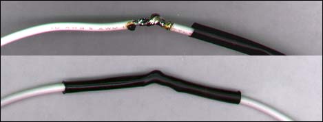
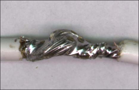
Soldering:Soldering is
probably the most secure way of connecting 2 wires (if
it's done properly). The photo below shows an in-line
solder connection. The wires were stripped back
approximately 3/4". Each wire was then bent,
roughly, into the shape of a fish hook. They were then
'hooked' onto one another and the end of the wires were
twisted back around themselves. They were then soldered
together. Both physically and electrically, this is a
very strong connection. Of course, this method requires
that we insulate the connection. Here I used heat shrink
tubing to insulate it. I could have also used electrical
tape. The second image is a close-up of the solder joint.
The little yellow drops are solder flux.
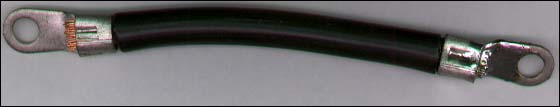
The image below shows a piece of 6g
wire with 2 ring terminals. One end is only crimped
(which provides a very good connection). The other end is
crimped and soldered. This provides an electrical
connection that's about as good as it can get. One thing
that you should keep in mind. Solder has a fairly high resistance compared to copper. This means that you
shouldn't rely on solder alone for a good connection. It
has to be crimped also. The larger image shows how well
the solder flowed. It actually flowed back under the
insulation. To do this, you need a very hot iron. A
propane torch won't work well because it causes oxidation
and will not allow the solder to 'stick'. The solder will
just roll off of the oxidized copper. If you have to use
a propane torch, heating the terminal from the back side
(opposite the wire) will reduce the oxidation of the
copper.
Connector
Quality: There are many low
quality connectors on the market. Many of the types you
get in cheap connector sets (with cheap crimping pliers)
are made so cheaply with so little metal that they can
NEVER make a good crimp. These are some other things that
make good quality connectors. The best connectors have
all of these features.
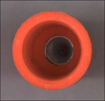
Funnel
Entry Insulators:
Funnel entry is simply where the insulator forms
a funnel inside of the insulator so that the wire
doesn't catch on the edge of the copper connector
as you insert the wire. If you are going to make
a lot of connection, this is absolutely
necessary.
Brazed
Seams:
When most connectors are made, they are stamped
from a flat sheet then formed to make a round
connector. When this is done, the part where the
2 pieces meet can be left as_is or they can be
brazed or soldered together. When this is done,
it provides for a much more secure crimp (because
the seam can't pull apart - which would relieve
pressure on the crimp/wire). The seam on the
large 6g connector (the one that was used to show
a soldered connection) has a brazed seam.
Nylon
Insulators:
Nylon insulators are somewhat tougher than PVC
insulators. When crimped too hard, PVC often
splits or breaks up. Nylon is much less likely to
split or break apart. The leftmost red spade
terminal and the rightmost blue push-on terminal
have nylon insulators. The rest of the insulated
terminals have PVC insulators.
Basic
Head Unit and 2 Speaker Installation: This page will deal mainly with the
electrical aspects of an installation. Physical aspects
like mounting and bracing won't be covered in any detail.
OK, these are the electrical connections that will have
to be made. This assumes that there was an OEM stereo in
the vehicle and it did NOT have external amplifiers.
Ignition (switched 12 volt
source - goes on and off with the key)
Ground
Left Speaker +
Left Speaker -
Right Speaker +
Right Speaker -
Power Antenna Remote (if the
vehicle has a power antenna)
Antenna (arial)
All of these connections should be
made using butt connectors and an aftermarket wiring
harness adapter (shown on the 'head unit' page). You'll
connect the new head unit's wires to the adapter harness.
This will allow you to make all connection while leaving
the stock harness intact. Some vehicles require antenna
adapters. Check with your car audio dealer to see if you
need one. If you have an older vehicle, it may have
common grounded speakers. If this is the case, you will
need to run new wires to the speakers. If in doubt, run
new speaker wires. If you run new speaker wires, you'd
connect the speaker output wires from the head unit
directly to the new speaker wires.
Things
You'll Need for a Basic Installation:
Strippers/Crimpers
Butt Connectors (red are most
commonly needed for OEM wiring)
Speaker Wire (16g parallel zip
cord is fine)
Tools to Remove the Head Unit
(#2 Phillips screwdriver, 7mm nutdriver, a Torx
T15 driver and a broad tipped regular screwdriver
will get you a long way)
DIN Radio Removal Tool* ('U' shaped tool required to remove
many of the newer car stereos - particularly Ford
and Mazda)
*These tools are inserted into the 4
holes on your head unit (2 on each side). After
inserting them, you pull them apart (away from
the center of the head unit) and out toward you.
Make absolutely sure that you've NOT inserted the
tool on the radio side of latches. They MUST go
to the outside of the spring latches. If they go
to the between the radio and the spring latch and
you bend the latches too far out, you may have to
tear the dash apart to get the head unit out. The
following demo may help.
Adding
an Amplifier:
If your head unit has
RCA/preamp outputs, adding an amplifier will be
pretty straightforward. It will take a little
effort but nothing really too difficult. The
hardest part is running the new power wire from
the battery to the trunk (boot) of the vehicle.
And no, you can't connect the amplifier's main
power wire to the vehicle's fuse box. These are the additional
connections that you'll have to make:
Main Power Wire:
The main power wire must be connected to the battery. It must have an
appropriately rated fuse in line (near the battery).
The wire will have to pass through a
grommet in the firewall, under the carpet
and (generally) into the trunk. To get
the wire into the trunk, you may need to
remove the back seat. When you run it
into the trunk, it generally has to pass
over some sharp sheetmetal. If this is
the case, take a piece of rubber heater
hose and split it open. Open the hose and
place it over the sharp sheetmetal. This
will prevent it from cutting the wire.
When making the connection to the
battery, you'll usually use a large ring
terminal. From the ring terminal you'll
use a short length of wire to connect to
the fuse holder. From the fuse holder,
you'll run the power wire to the rear of
the vehicle. In the rear of the vehicle,
the power wire can be run either directly
to the amplifier's positive terminal (if
you have only one amplifier) or to a
distribution block (if you have multiple
amplifier).
Signal:
The amplifier needs some sort of signal
to amplify. The best way to send it a
signal is through the RCA cables. If your
head unit does not have preamp outputs, I'd recommend using
a Line Output Converter (LOC). Since you may not have any
trouble shooting skills, the LOC is
probably the best way to avoid trouble.
Many times, the speaker level input of an
amplifier will be poorly designed and
will cause noise problems. There have
even been a few speaker level inputs on
amplifiers with a common ground input
(very bad). Using the LOC avoids these
problems.
Remote Power:
The remote wire from the head unit
tells the amp when to turn on and off. It
is a low current control signal that runs
from your head unit to the amplifier. It
must be fused behind the head unit with a
0.5 amp fuse (1/2 amp).
Ground:
The ground from the amplifier will be a
short run of cable approximately the size
of the amplifier's incoming power wire.
It will be grounded to the floor pan of
the vehicle. The amplifier page has more details on
getting a good ground.
Speaker Wires:
The speaker wires will run from the
amplifier outputs to the speakers. For
connecting the amplifier to woofers in
the trunk, a short run of 16g speaker
wire will be fine. If you're connecting
the amplifier to interior speakers
(doors, dash, back deck), you must make
sure that there are no inline OEM
amplifiers. If there's any doubt, run new
wires.
Note:
Any speakers that will be
connected to the amp MUST be disconnected from
the head unit. Sending the amplifier's output
signal back into the speaker outputs of the head
unit will frag the head unit (at least a $90
repair bill).
Multiple
Amplifiers:
When using multiple amplifiers,
you'll have to do as above but a few more things
come into play.
Power Wire:
The power wire will probably have to be
larger. That's why it's good to look
forward to what you want for your system.
If you run a wire that's barely large
enough for one amplifier, adding a second
amp will require running a second wire
(with its own fuse holder) or will
require that you replace your existing
wire. To find out what wire you need, you
can use the calculator(s) on the 'wire' page of the site. You'll
enter the total power and a few other
things and they will tell you the proper
wire size. To split the power source to
each amplifier, you'll need to use a
distribution block. I recommend fused
blocks for splitting the 12 volt line and
only UNfused blocks for ground.
Electronic Crossovers:
When using multiple amplifiers, you
generally split up the audio spectrum.
This allows you to send the bass to
larger speakers and the rest of the audio
spectrum to interior speakers. Many
amplifiers have built in crossovers and many of them are quite
good but some are VERY poor. The poor
ones generally have poor rolloff
characteristics. Using a good quality
external crossover solves this problem,
It also puts all of the controls (level,
crossover frequency, phase...) in one
place. An external crossover also
generally has more features than the
crossovers built into the amplifiers.
This can make it much easier to adjust
the system.
Signal:
When sending the signal to a single
amplifier, you simply plug them directly
into the amplifier. When you have
multiple amplifiers, you have to get the
signal to all of them. If you have only
one pair of RCA cables, you can use y-cables. If you're using an external
crossover, you can plug the RCAs into the
input of the crossover. The crossover
will then have multiple outputs. The low
pass output will go to the bass amp. The
high pass output will go to the highs
amp. No y-cable will be needed unless you
have multiple bass amps or multiple highs
amps. Some amplifiers provide a
pass-through or crossed over preamp
output to go to another amp. This will
also avoid the need to use y-cables.
Remote:
Since the remote signal is such a low
current signal, it's perfectly fine to
jump from amplifier to another with a
relatively small wire (it's NOT OK to do
this with power and ground). I recommend
using nothing smaller than 16g because
it's easier to get good connections with
it than it is with very small wire. You
'could' use 22g but it's more likely to
break and may not be held firmly by the
clamps in the terminal block. This is
especially important when the amplifier
has tubular connectors with set screws.
Misinformation &
Ignorance‡
The following few things are
commonly misunderstood:
Clipping:
Many people don't understand 'clipping'.
Some say their amplifier is clipping when
it's cutting out or cutting off. That's
not clipping. Clipping occurs when an
amplifier is driven to attempt to produce
more output voltage than what's available
from the power supply. The following
shows what a clipped signal looks like.
It's kinda what would happen if you were
jumping on a trampoline inside your home
(with 8' ceilings). You would only be
able to jump so high then your head would
hit the ceiling (the ceiling is analogous
to the rail voltage in the amplifier). No
matter how hard you jump, you can not go
higher than the ceiling (assuming you
don't have a really hard head). See the Amplifier, Too
Little Power
and Setting Gains with a Scope pages for more detailed info
(AFTER you finish reading this page).
Head Unit Power Output:
Many manufacturers inflate/exaggerate
their specs/ratings. This is especially
true for power amplifiers. Many head
units claim that they can produce 40+
watts/channel. In fact, the true usable
power is generally no more than 20 watts
RMS per channel into a 4 ohm load.
2 Volt vs 4 Volt Preamp
Outputs:
It is not necessary to have 4 volt preamp
outputs to have a good sounding system.
The quality of the head unit is much more
important. I would much rather have a 2
volt out Alpine or Pioneer than a 4 volt
out bargain-brand head unit.
Distortion in Head Unit
Amplifiers:
Many people claim that the head unit's
internal amplifier is 'dirty'. This just
isn't true. For the most part, the
distortion levels are inaudible at any
point up to the point of clipping. The
reason that they believe that the
internal amplifiers are distorted is
because they need more than 20 watts per
channel and they are driving the internal
amplifiers into clipping. When they add
an external amplifier, the external
amplifier can produce more power before
clipping than the internal amplifier
could produce before clipping. This means
that the external amp can play at the
desired level without audible distortion.
If both the internal and external
amplifiers were played at the same level
(neither clipping), the internal and
external amplifiers would sound precisely
the same (disregarding any equalization
or filters that may be available on the
external amplifier).
Speaker Wire Size:
It is not necessary to run large gauge
speaker wire to have good quality sound.
16g lamp cord is perfectly fine in almost
every situation. Even the stock wiring in
the car is usually perfectly fine (the
exception may be only when there are OEM
amplifiers in line with the speakers). If
someone tells you that you have to
replace the stock speaker wires with
large gauge wire to have good sound
quality, they probably don't know what
they're talking about.
Dual Voice Coil
Woofers:
Dual Voice Coil (DVC) woofers are simply
speakers with two voice coils wrapped
around the same voice coil former. This
allows the speaker to be connected in 2
different ways. With the individual coils
wired in series, the resulting impedance
will be 2 times the impedance of each
individual coil. Wiring the coils in
parallel will make the impedance 1/2 the
impedance of each individual coil. This
means that a speaker with dual 4 ohm
coils can be wired to 2 ohms or 8 ohms.
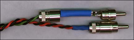
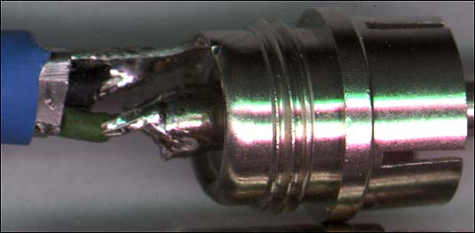
Expensive Patch Cables:
It's not necessary to have $20/foot
interconnects in your vehicle to have
good sound quality. It's not even
necessary to have shielded cable in all
situations. Many people make their own
preamp cables out of 20g or 18g primary
wire. They take 2 single conductor
stranded wires and twist them together
with a cordless drill until they have 1-2
twists per inch. Then they simply solder
the RCA connectors on the ends of the
cable. Even cheap, thin RCA cables will
work perfectly fine most of the time. If
the audio equipment that you have has
well designed input circuits, expensive
cables are simply not needed. The
following cable is an example of twisted
pair cable. The connectors aren't shiny
and gold plated but are
of the highest quality. They are made by Switchcraft.
Large Electrolytic
Capacitors:
I've never seen
any proof anywhere that a large capacitor does anything to
improve the quality of the
amplifier's output. Some people
claim that they help to prevent
your headlights from dimming but
in most cases it's simply a
placebo effect. If the capacitors
did what they were supposed to
do, every capacitor manufacturer
would have a demo vehicle showing
how the output changed by xdBs
when the caps were in or out of
the circuit. To my knowledge, no
company has proven that they do
anything. Take the money that you
would spend on a capacitor and
spend it on an alternator
upgrade.
Capacitors do
not increase the voltage at the
amplifier. The capacitor's
voltage will be equal to the
battery and charging system
voltage. If the voltage at the
battery falls below the
capacitor's voltage, the
capacitor will instantly
discharge into the battery until
their voltage is again the same.
Unless there is some significant
resistance in the power wire
between the cap and the battery
(with no load on the power wire),
there's no way for the voltage
between them to be different. If
there's a load on the power wire
(an amplifier drawing current),
the voltage at the cap and
amplifier will be lower than it
is at the battery. Read the capacitor page for more
detailed info.
Gains:
The gain controls do NOT limit the output
power of your amplifier. If you turn your
gains to their middle position, the
amplifier will still produce full power.
It will just take a little more input
signal to make it do so. The gain
controls won't necessarily prevent
clipping. It's true that they can be set
to prevent clipping but given enough
signal, the amplifier will be able to be
driven into clipping regardless of the
position of the gains. Do a site search
for 'gains' for more info.
Volume Control
Position:
Just because your radio's volume control
can go to 60, that doesn't mean that it
can do so and remain distortion free.
This is especially true when the bass is
boosted to it's maximum position. The
preamp outputs generally remain
distortion (clipping distortion in this
case) free for more of the volume
control's range than the speaker level
outputs. Many times, the speaker level
outputs are driven into clipping at
anything higher than 50% of the volume
control's range (even with the bass set flat).
Relays as Buffers:
Since the remote control/power antenna
output of the head unit is limited in the
current that it can supply, it can not be
used to drive a fan (or other non-audio
control circuit) directly. To drive the
fan (or neon or strobes or...), a relay must be used to buffer the
remote output. Even if the remote is
capable of driving the fan initially, it
will eventually do significant damage to
the remote output driver circuit. If the
remote wire is allowed to contact ground
AND the head unit is on AND it's not
properly fused, it will damage the head
unit severely enough to require a trip to
a repair center (2-3 weeks without your
head unit and $40-$60 of repair and
shipping charges). It will take less than
one second to do the
damage. If the remote wire isn't
connected to an amplifier's remote
terminal (if it's just lying loose in the
vehicle), tape it up or otherwise
insulate it.
Stereo vs Mono:
Some people believe that a system can't
be 'mono' unless the speaker (or
speakers) is bridged onto the amplifier.
If you have a 2 channel stereo amplifier
and the same signal is driven into each
channel, the output is mono (regardless
of the number of channels or the number
of speakers). To be true 'stereo', the
signals driven into the left and right
channels have to be different from one
another.
Mono Amplifiers:
Many mono amplifiers have 4 speaker
output terminals (two positives and two
negatives). Lets compare a stereo
amplifier capable of driving a 2 ohm load on each channel to a
mono amplifier capable of driving a 2 ohm
load. Let's say that we have four 4 ohm
speakers. If we want to run all 4
speakers on the stereo amplifier, we
would simply connect 2 speakers to each
channel. Now, when we look at the mono
amplifier amp with 4 speaker terminals
(the same number as the stereo
amplifier), you might think that you can
connect 2 speakers to each pair of
speaker terminals. The problem is... the
speaker terminals inside the amp are
connected together in a parallel configuration (2 positives
together 2 negatives together). So, if we
connect 2 speakers to each pair of
speaker terminals on the amplifier, we
actually have a 1
ohm load.
You can check to see if the terminals are
in parallel with an ohm
meter.
Speaker Magnet Size:
Just because a speaker has a very large
magnet, that does NOT mean that it's a
great speaker. Many times, having a very
large magnet just means that the speaker
will be harder to drive. Many speakers
use huge magnets to get you to buy them
but the design is inferior to many of the
truly great speakers like JL. There are
many variables that determine speaker
performance. Magnet size is just one
variable.
Speaker Power Ratings:
Having a speaker with very high power
ratings (even if the power
ratings
are legitimate) doesn't necessarily make
it a good speaker for every application.
Competition speakers that have huge
magnets and can truly handle thousands of
watts of power may not be the best choice
for a moderately powered system. Speakers
that are designed to handle 1000 watts of
power probably will not be a good choice
for those with only 200 watts of
amplifier power. In many instances,
having speakers that are honestly rated
to handle about the same power as your
amplifier's rated power output will
perform best.
Speaker Enclosure
Types:
You'll hear many people tell you that one
type of speaker
enclosure
is 'best'. Unless they give specifics,
don't believe them. Sealed, ported and
bandpass enclosures all have pros and
cons. Some are better in some situations
but there's no one 'best' for all
applications.
Speaker Enclosure Size:
I get a lot of email concerning subwoofer
enclosure size. Most want to know if the
enclosure will work if it is different
(larger or smaller) from the
'recommended' size. The answer is yes in
virtually all cases. If you vary the size
of the enclosure, the frequency response
will change and it will perform
differently but 'different' doesn't
necessarily mean 'worse'. If the
enclosure is within ~±10%, you will not
hear a difference. The only time that I
know of that you'll have a problem is
when the woofer will be driven with
extreme power. Some speakers (like the
Kicker Solobarics) need a smaller
enclosure when they will be driven with
extreme power. This allows the air in the
enclosure to better damp the cone
movement. If they are used in an
enclosure that is too large, the
suspension will be stressed which may
lead to premature failure. Please note
that this is not exclusive to the
Solobarics. They are simply the woofers
that came to mind.
Sealing Speaker
Enclosure Joints/Seams:
It is NOT necessary to use silicone (or
any other sealant) to seal the joints in
an enclosure if the wood glue fills all
of the seams (which it will do if you
make accurate cuts). Using silicone or or
other sealants can damage some woofers if
the woofer is installed before the
sealant has cured or before all of the
solvents have evaporated. This can take
as long as a couple of days for some
sealants. This is how tight the joints
should be:
Dividers in Speaker
Enclosures:
In virtually all applications, a speaker
enclosure will be better (overall) if it
has dividers between chambers. The
dividers make the enclosure more rigid
(which is always desirable). The dividers
also allow you to continue playing your
other sub (or subs) if one goes out.
Equalizers:
An equalizer is NOT designed to make a
system louder. It's designed to correct
errors in the overall frequency response
of the system. There is no predefined
'correct' way to set the controls on an
EQ. A 'smiley face' is RARELY the correct
setting. The correct boost/cut for each
band will vary significantly from system
to system. It is not necessary to use the
sliders at their maximum or minimum level
unless there is a significant deficiency
somewhere in the system. On many high
quality systems, the required boost or
cut may not exceed a few dBs. For a 1/2
din EQ, this may mean that the slider may
not have to move more than 1/8 of an inch
from it's center position to achieve the
desired correction. If someone has their
EQ boosted to it's maximum position, it's
likely that their system has significant
problems (or they don't know what they're
doing).
Amplifier Bridging:
It is NOT necessary to bridge an
amplifier to get full power from it.
Running an amplifier at 2 ohms stereo
will produce the same power as running it
at 4 ohms mono. Running an amplifier at '2
ohms mono' will generally mean the end
to it (exceptions - class
D and high
current
class A/B amplifiers).
2 Ohm Stable:
When a multi-channel amplifier (2 or more
channels) says it's two ohm stable, this
generally means that it can drive a two
ohm load with each channel. This doesn't
mean it can drive a two ohm load when the
amplifier is bridged. If it is two ohm
stereo stable it is generally going to be
able to drive only a 4 ohm (or higher)
load when bridged.
What Can My Speakers
Handle?:
This question gets asked a lot and the
following is my generic answer:
If you want to
drive your amplifier up to (but
not generally into) clipping, the
speakers need to be rated to
handle the same power as the
amplifier can deliver.
If you're going
to get stoned or drunk or if you
don't have any ability to detect
when there is a problem and will
constantly drive your amplifier
into hard clipping, your speakers
must be rated to handle twice the
RMS power that the amplifier can
produce cleanly (before
clipping).
If you have a
good deal of common sense and
will listen closely to the
speakers for stress (amplifier
clipping, suspension bottoming
out, popping...), you can
probably use virtually any
amplifier available.
Keep in mind that it's
virtually impossible to listen for stress if the
speakers are in the trunk or in a bandpass
enclosure. In either instance, it may be
difficult to hear when something isn't quite
right.
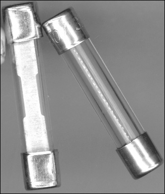
Fuses:
Just because a fuse
fits in the fuse holder, that doesn't mean that
it's the right fuse. Fuses have current ratings.
The replacement fuse must have the same current rating as the one specified by the
manufacturer. The 2 fuses below look alike but
are very different. If you look closely at the
element, you can see that one is much larger than
the other. The larger element can continuously
pass much more current than the smaller one.
Blowing
Fuses:
The following demo will help with common
instances where fuses blow. The little green
indicators show whether voltage is present or
not. If it's bright, there is voltage present.
When dark, there is no voltage on that point in
the circuit. When a fuse is blown, there is
voltage on only one side of it. When the fuse
isn't blown, the voltage is the same on both
terminals of the fuse.
Click HERE
to make this demo fill this window.
You'll have to use the back 'button' to return
here.
Main
Power Line Fuse:
If you have to work on any part of your stereo
system (especially the amplifiers), you MUST
remove the main power fuse from the fuse block at
the battery. If you accidentally ground the power
wire, the fuse will blow which may cost as much
as $10 to replace. If you short the screwdriver
to the case of the amplifier (or any other
electrical component) the piece of electronic
equipment may be severely damaged. Even if the
amplifier has on-board fuses, there may still be
some serious damage.
Disconnecting
the Battery:
When installing a new system in your vehicle, you
should remove the GROUND wire from the battery.
It will prevent you from doing any damage to the
vehicle's electrical system. It will also prevent
your battery from being drained by the
dome/hood/door lights. I know you want to listen
to the radio while running all of the new wires
and such. Do yourself a favor and GO FIND ANOTHER
RADIO.
RCA
Shield Ground:
The RCA shield (the shiny outer conductor) is
connected to ground inside the head unit. The
connection is made by a very small copper trace
on the circuit board. If the shield ground comes
in contact with any source of power, the copper
trace will be burned open and the RCA outputs
will not work properly (until the head unit is
taken in for repair). If you have a loose pair of
RCA jacks or power wire sliding around in your
trunk and they come in contact with each other,
the head unit will be damaged instantly.
12dB/Octave
Passive Crossovers:
You may not know what a twelve dB per octavepassive
crossover is yet
but it is explained in detail on the site. This
section is a warning. If you have a 12dB/octave
passive crossover (the type included with
virtually every component set), and you blow a
speaker (tweeter, midrange, midbass - it doesn't
matter which), you MUST
NOT play your system
until the crossover is disconnected from the
amplifier OR the blown speaker is replaced. If
you continue to drive a signal into the
crossover, there is a VERY good chance that the crossover
and/or the amplifier will suffer catastrophic
damage. This is NOT the crossover's fault. The problem
is that a crucial component of the circuit is
missing, causing the circuit to act completely
differently. Using the crossover without having
working speakers on ALL of the outputs will cause the
crossover to act as a direct short at the
crossover frequency of the missing speaker.
People can't understand why a crossover melts
down when it was perfectly fine when checked just
after the tweeter failed.
‡Ignorance: Not Knowing. Everyone is
ignorant of something. No one can know
everything.
Equipment
Manufacturer Recommendations:
I don't have any affiliation
with any manufacturer listed below. The
recommendations are purely personal opinion and
experience. Don't email me to argue about the
best in any particular category.
Amplifiers: Rockford
I know that people like to say that
Rockford is garbage but in nearly 20
years of doing repair work, I haven't
seen another manufacturer deliver a
product of such consistently high
quality. Plus... It's made in the US.
Head Units: Alpine
Great quality, reliability and sound
quality.
Speakers: Pioneer and
JL
At the low end of the price spectrum,
Pioneer consistently delivers across the
board. At the low to mid price level, JL
is consistently good.
Consider Yourself Primed
As I said at the top of the
page, this is a primer that just lightly touches
on the basics. You should now have some idea
what's involved in installing or upgrading a
basic audio system. If anyone feels that I left
anything important out of this page (things that
would prove helpful to newbies), please let me
know. From this point, I'd suggest going through
the rest of the directory in order (hey, but who
listens to me? :). Don't try to learn everything
in one day and don't get discouraged if you have
to read something more than once to understand
it. I can assure you that I don't fully
understand everything the first time I read it.
Also remember to read from other sites. If you
don't understand something here, it may be
explained in a way that better suits you on
another site.
If you find a problem
with this page or feel that some part of it needs
clarification, E-mail
me.