Please 'Boom' Responsibly As most of you have noticed, the noise ordinances have become much tougher lately. Most of this is due to idiots, yes IDIOTS, who drive through residential areas with their windows down while their system is playing at full power. To make things worse, the music they listen to has all sorts of foul language that's not suitable for small children, (who may be playing outside). There are even a few people, who are even beyond idiot status, that play their systems at full power through residential areas after 10:00 PM (when many people go to bed). I don't believe that this type of behavior is good for the industry. If the fines get too stiff, people will stop buying large systems. If this happens, more people will get out of car audio (who wants a mediocre system). People get interested in things because they're exciting. A deck and four 6.5" speakers are not going to interest many of the younger car audio enthusiasts. If car audio enthusiasts keep annoying more and more people, the fines will keep getting tougher. All of this will only reduce interest in the equipment that fuels the industry. If you want to listen to your system at full volume, get out on the highway where there's little chance of bothering anyone. When you get to a red light, turn it down. If the only thing attractive about you is your 'system', you have some work to do. Bottom line... Think about what you're doing. Think about other people. It's not the end of the world if you have to turn the volume down for a little while. |
| Passive Crossover
Basics High Pass Crossovers Below there are 4
different crossover configurations. The graph in the
middle of the 4 systems shows the slopes for 6dB (first order), 12dB (second order), 18dB
(third order) and 24dB (fourth order) per octave crossovers. The crossover components' colors
match its corresponding curve on the graph.
Low Pass Crossovers Below there are 4
different crossover configurations. The graph in the
middle of the 4 systems shows the slopes for 6dB (first
order), 12dB (second order), 18dB (third order) and 24dB
(fourth order) per octave crossovers. The crossover
components' colors match its corresponding curve on the
graph.
You can see that the higher order crossovers are more complex and harder to build but they also provide a steeper slope. It is not necessary to use a high order crossover to have a great sounding speaker system. Every system has unique requirements to achieve the best sound quality. The installer must determine which type will work best (that's why they get the big bucks :-). |
| Comparing Different
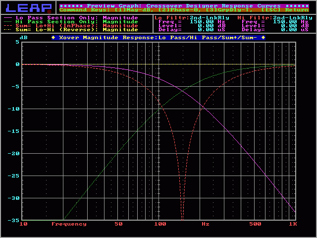
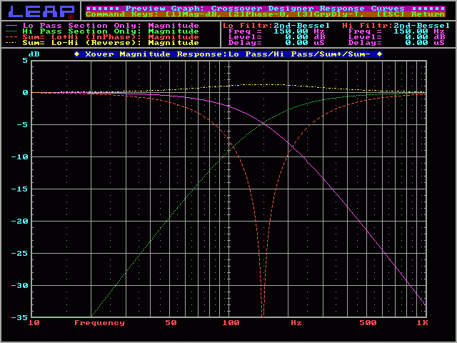
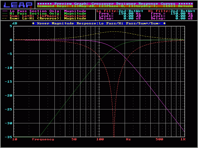
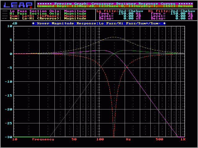
Filter Types The previous calculator determines the values for a 2nd order (12dB/octave slope) Linkwitz-Riley crossover. This type of crossover is very common because of it's flat response when the high and low frequency power outputs are summed. This is important to prevent a dip or peak in the acoustic power response of the speakers (it provides a flat frequency response at the crossover point when driving both high and low frequency drivers).
|
|
||||||||||||
2nd order Linkwitz-Riley: In the following graph, you can see the response for both the high and low frequency drivers. You can also see that the crossover point is 150hz. As previously noted, the on-axis acoustic output of a L-R crossover has a flat response at the crossover frequency. To do this, the crossover point has to be 6 dB down. Since there are 2 drivers (a midrange and a woofer) operating at the crossover point and they presumably have a comparable output and they are receiving the same power (both 6dB down from full power), the output (their summed on-axis acoustic output) will be as if a single driver were playing at the crossover point. This will provide a flat overall frequency response at the crossover point. |

|
|||||||||
|

|
|||||||||
|

|
|||||||||
|

|
|||||||||
Open Crossover Output Warning
You may damage your amplifier if you drive a second (or higher) order crossover when the speaker's voice coil is open (the speaker is blown) or if no speaker is connected to the crossover's output. When the speaker is removed (or the voice coil opens), the circuit becomes a resonant circuit. This circuit will, at the crossover frequency (or some multiple of the crossover frequency), present a 0 ohm load to the amplifier. The actual resistance will be only the resistance in the speaker wire and the inductor. Any time that there is audio at the resonant frequency, the amplifier will be stressed the same as if the speaker wires were shorted together. This will drive some amplifiers into protection. Others will blow a fuse or die a horrible painful death. The following graph shows how the impedance of the normal circuit (violet line) never drops below 4 ohms (the speaker's impedance). It also shows how the impedance of the circuit without a speaker (yellow line) drops to 0 ohms at the crossover frequency (for a 2nd order crossover, the resonant frequency is the same as the crossover frequency).
Correcting Passive Crossover Problems
|
You should remember:
1.A passive crossover requires no external power source to
operate.
2.A passive crossover uses caps, coils and resistors to attenuate
the signal level above and/or below a certain frequency.
| If you find a problem
with this page or feel that some part of it needs
clarification, E-mail
me. This is a link to this site's home page. |
calculator