- Amplifier Classes:
- Most mobile amplifiers use
complementary transistor pairs to drive the
speakers. In this configuration there is a
transistor (or group of transistors) which
conducts current from the positive power supply
voltage for the positive half of the audio
waveform and a different transistor (or group of
transistors) which conducts current from the
negative power supply voltage for the negative
half of the waveform. There are some amplifiers
which use the same transistor(s) to drive both
the positive and the negative halves of the
waveform.
- NOTE:Amplifiers in classes A,
B, and AB operate their output transistors in a
'linear' mode. Class 'D' amplifiers operate their
outputs in 'switch' mode.
-
- Mode examples:
-
- Linear mode:
- Imagine that you are the
amplifier's output device(s) and you must support
a 10 pound iron weight (the speaker load). The
most difficult method (linear mode) would be to
hold the weight straight out in front of you.
This would very roughly simulate the linear mode
architecture. Your muscles would start to ache in
a short amount of time. Think of this pain as the
power dissipation in output transistors.
- Switch mode:
- In this example, you can
support the weight in one of two positions. In
the first position, you can hold the iron weight
directly over your head with your elbows locked
so that your're not really using very much effort
to support the weight. In the second position,
you would let the weight hang down by your side.
This would also use very little effort from your
muscles. If you held it directly over your head
half of the time and by your side for the other
half of the time, it's position would 'average'
out to be the same as if you held it out straight
in front of you like in the previous (linear
mode) example. This would roughly simulate the
switch mode which we will discuss later in this
page. You can see that with this method (switch
mode), there would also be little pain (power
dissipation) involved in supporting the weight.
- CLASS 'A'
- Many class A amplifiers use the
same transistor(s) for both halves of the audio
waveform. In this configuration, the output
transistor(s) always has current flowing through
it, even if it has no audio signal (the output
transistors never 'turn off'). The current
flowing through it is D.C. A pure class 'A'
amplifier is very inefficient and generally runs
very hot even when there is no audio output. The
current flowing through the output transistor(s)
(with no audio signal) may be as much as the
current which will be driven through the speaker
load at FULL audio output power. Many people
believe class 'A' amps to sound better than other
configurations (and this may have been true at
some point in time) but a well designed amplifier
won't have any 'sound' and even the most critical
'ear' would be hard-pressed to tell one design
from another.
NOTE:
Some class A amplifiers use complimentary
(separate transistors for positive and negative
halves of the waveform) transistors for their
output stage.
- CLASS 'B'
- A class 'B' amplifier uses
complimentary transistors for each half of the
waveform. A true class 'B' amplifier is NOT
generally used for audio. In a class 'B'
amplifier, there is a small part of the waveform
which will be distorted. You should remember from
an earlier page, that it takes approximately .6
volts (measured from base to emitter) to get a
bipolar transistor to start conducting. In a pure
class 'B' amplifier, the output transistors are
not "biased" to an 'on' state of
operation. This means that the the part of the
waveform which falls within this .6 volt window
will not be reproduced accurately. The output
transistors for each half of the waveform
(positive and negative) will each have a .6 volt
area in which they will not be conducting. The
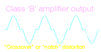
distorted part of the waveform is called
'crossover' or 'notch' distortion. Remember that
distortion is any unwanted variation in a signal
(compared to the original signal). The diagram
below shows what crossover distortion looks like.

- CLASS 'AB'
- As we said earlier, a class 'A'
amplifier is very inefficient. This is not good
for a car audio amplifier. We also said that a
class 'B' amplifier will cause a signal to be
distorted, which is not good in any audio
amplifier. A class 'AB' amplifier is the best
compromise. A class 'AB' amplifier is a class 'B'
amplifier which has a small
amount of "bias" current flowing
through the output transistors at all times. This
eliminates virtually all of the crossover
distortion. The bias current is flowing because
the output transistors are always conducting
current (even without an audio signal). This
differs from a pure class 'A' amplifier in the
amount of current flow. A pure class 'A'
amplifier has an enormous amount of current
flowing through its output transistors with NO
audio signal. A pure class 'B' amplifier has NO
current flowing through its outputs with no input
signal. A class 'AB' amplifier is much more
efficient than the class 'A' but without the
distortion of the class 'B'. MANY of the car
audio amplifiers which claim to be a class 'A'
amplifier are just a high bias class 'AB' design.
These amplifiers are only class 'A' at very low
power output levels. At higher power levels, one
of the output transistors will switch off while
the other output transistor is conducting. I
don't want you to think that I am telling you
that there are no class 'A' amplifiers. There are
a few high quality
mobile amplifiers which are a true class 'A'
design.
- CLASS 'D'
- We said that class 'A'
amplifiers were VERY inefficient. Class 'AB'
amplifiers are also inefficient but are more more
efficient than class 'A' amplifiers. Class 'AB'
mobile amplifiers are generally 60% efficient
when driving a 4 ohm load at maximum power (just
before clipping). The reason that these amplifier
configurations are inefficient is because there
is a difference of potential (voltage) across the
output transistors and current flowing through the output
transistors. When you have voltage across the
device and current flow through the device,
there will be power dissipation in the form of
heat. The power needed to produce this heat is
wasted power. When there is (virtually) no
voltage drop across a device (such as a large
piece of wire or a transistor), there can be a
significant amount of CURRENT flow through the
device with (virtually) no power dissipation.
This means that there is virtually no heat given
off (highly efficient). The inverse is also true.
If you have a significant amount of VOLTAGE
across the device (transistor, wire...) but no
current flow through the device, again, there
will be no wasted power.
OK, now to the point. A class 'D'
amplifier, which may also be known as a switching
amplifier or a digital amplifier, utilizes output
transistors which are either completely turned on
or completely turned off (they're operating in
switch mode). This means that when the
transistors are conducting (switched on) there is
virtually no voltage across the transistor and
when there is a significant voltage across the
transistor (switched off), there is no current
flowing through the transistor. This is very
similar to the operation of a switching power
supply which is very efficient.
- Output transistor switching:
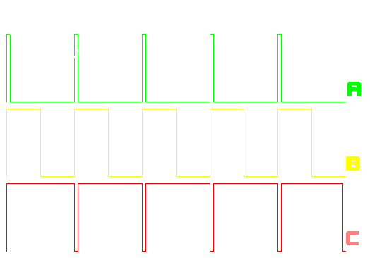
- In the diagram below, there are
3 waveforms. Point 'X' is the point where the
transistor would be fully 'on', it would be
conducting the full power supply voltage.This is
the same as taking a piece of wire and connected
the rail voltage to the speaker output of the
amplifier. Point 'Y' shows that the transistor is
fully 'off' and the output voltage is effectively
0 volts. This is the same as completely
disconnecting the speaker from the amplifier. The
'duty cycle' of waveform 'A' is approximately
10%. If you averaged the voltage over time, the
effective output voltage would be approximately
10% of the power supply voltage. Waveform 'B' has
a 50% duty cycle. Waveform 'C' has a 90% duty
cycle.

- Note:
- This diagram (below) shows the
effective D.C. output from the respective
waveform. Please keep in mind that the effective
output voltage is represented as it would be
while there is a
'load' on the amplifier's output transistors. If
there were no load, the output voltage would stay
at the full power supply voltage because nothing
would pull the voltage back toward the reference
(ground).
- Averaged DC voltage:
- You should notice that the
longer the output transistors are 'on', the
higher the effective output voltage. From a
purely mathematical stand point, the output of
the top waveform is at 100% of the supply's
output voltage for 10% of the time and at 0% (0
volts) for 90% of the time. If we assume that the
amplifier has a rail voltage of 40 volts, the
output is at 40 volts for 10% of the time and at
0 volts for 90% of the time. This would give you
((10*40)+(90*0))/100 or 4 volts of average output
voltage.

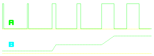
- In the diagram below, waveform
'A' is the pulse width modulated portion of an
audio signal. Notice that it switches between the
yellow reference line (ground) to the rail
voltage (white line).

- Waveform 'B' shows how the
voltage is stepped up as the width (time on) of
the pulse increases. This part of the signal is
not really present at any point in the amplifier.
It is simply included for clarity. You should
notice how the effective voltage is stepped up as
the pulse width increases.

- Waveform 'C' is a portion of
the sine wave output signal, after passing
through a low pass filter. Keep in mind that the
pulses are a high frequency square wave, it may
be as high as 500,000 hertz. A low pass filter
which will allow a 20,000 hertz signal to pass
(the highest frequency needed to reproduce the
audio spectrum) will have virtually no effect on
the audio output signal and will completely
filter out the switching pulses.

- In the diagram below, notice
the circle on the sine wave at the bottom of the
drawing. It shows the portion of the sinewave
that is being reproduced in the example.

- The following animation shows
how the pulse width compares to the sine wave
equivalent and the angular equivalent (discussed
in the amplifier bridging page). You should note that the
horizontal scale of the square wave pulses is not
accurate. In reality, there might be 1,000-10,000
pulses for one complete cycle of the sine wave
(depending on the switching frequency of the
amplifier and the frequency of the sine wave).
You can see that the pulse width is of a high
duration to produce the higher voltage portion of
the waveform and of low duration when the voltage
is at its lowest point.
- The dark blue switching
transistors are shown in the semi-transparent
amplifier. They produce the square wave pulses.
The pulses are then sent to the low pass filter
which allows only the demodulated audio signal to
pass through to the speaker terminals of the
amplifier.
-
|