Please
'Boom' Responsibly As
most of you have noticed, the noise ordinances have
become much tougher lately. Most of this is due to
idiots, yes IDIOTS, who drive through residential areas
with their windows down while their system is playing at
full power. To make things worse, the music they listen
to has all sorts of foul language that's not suitable for
small children, (who may be playing outside). There are
even a few people, who are even beyond idiot status, that
play their systems at full power through residential
areas after 10:00 PM (when many people go to bed). I
don't believe that this type of behavior is good for the
industry. If the fines get too stiff, people will stop
buying large systems. If this happens, more people will
get out of car audio (who wants a mediocre system).
People get interested in things because they're exciting.
A deck and four 6.5" speakers are not going to
interest many of the younger car audio enthusiasts. If
car audio enthusiasts keep annoying more and more people,
the fines will keep getting tougher. All of this will
only reduce interest in the equipment that fuels the
industry. If you want to listen to your system at full
volume, get out on the highway where there's little
chance of bothering anyone. When you get to a red light,
turn it down. If the only thing attractive about you is
your 'system', you have some work to do. Bottom line...
Think about what you're doing. Think about other people.
It's not the end of the world if you have to turn the
volume down for a little while.
Regulated vs Unregulated Power
Supplies:
Note:
Before reading this page, you
should (at the very least) read:
The terms 'regulated' and
'unregulated' refer to the power supply control
circuits.
UNregulated Power Supply:
An unregulated power supply is
by far the simplest switch mode power supply
(SMPS) used in mobile power amplifiers. The
transistor(s) driving each half of the
transformer primary winding are driven at full
duty cycle. The duty cycle does not change during
normal operation. No matter how low or high the
battery voltage gets, the duty cycle will not
change. Unless, of course, the voltage gets too
low to operate. Then the supply control chip will
simply quit driving the power supply FETs (the
supply will shut down completely). Under normal
operating conditions, the no-load rail voltage
(amp idling, no audio out) will vary in direct
proportion to the battery voltage.
Unregulated Power supplies and
Changes in Battery Voltage:
As we mentioned above, the
battery voltage is not constant. It may vary from
11.5-12.5 volts with the engine off to ~14.4
volts with the engine running. If the battery
voltage is 12 volts and the transformer has a 1:2
ratio as in the previous example, the power
supply will produce ±24 volts. If the battery
voltage is 14.4 volts, the supply will produce
±28.8 volts (an extra 9.6 volts). This is why
amplifiers with unregulated power supplies have
significantly different power ratings with
different battery voltages. A change in battery
voltage directly effects the rail voltage. If the
output transistors were 100% efficient (they
aren't) and could deliver the full rail voltage
to the speakers, the following calculations show
you how the difference in battery voltage
produces different power outputs into a 4 ohm
speaker load.
Using
the formula:
P = E2/R
At 12 volts...
P = 242/4
P = 576/4
P = 144 Watts
(peak power)
At 14.4 volts...
P = 28.82/4
P = ~207 Watts
(peak power)
As you can see, there is a
significant difference in power output with the 2
battery voltages.
Stiffly regulated power
supplies
In an unregulated power supply,
the engineers simply use the transformer ratio
along with the primary voltage to determine the
rail voltage but battery voltage fluctuations
(and copper and core losses) cause the secondary
rail voltage to fluctuate. In a stiffly regulated
power supply, there is a circuit which
continually monitors the rail voltage and varies
the duty cycle to keep the rail voltage very
close or exactly at the target voltage. At no
point in time, under normal operating conditions,
will the rail voltage fall below the target
voltage.
The following demo shows the
duty cycle for both a stiffly regulated supply
and an unregulated supply under varying
conditions.
If, in a regulated power supply, we want a total
secondary target voltage of 48 volts (±24 volts) with a 12
volt battery voltage (as in the first example) we
could use a 1:2 ratio but as
soon as a load is placed on the power supply
rails (because you turned up the volume), the
rail voltage sags, even if the power supply
pushes the FET duty cycle drive to 50% (as high
as it can go). Why? The transformer doesn't have
enough ratio to overcome losses (due to
inefficiencies). If we increase the ratio to 1:3,
the control chip in a regulated power supply will
reduce the duty cycle to prevent overshooting the
target voltage (when there is little or no audio
output). Now, when current is drawn from the
power supply rails, the duty cycle is increased
just enough to maintain the target voltage. In a
stiffly regulated power supply, the transformer
ratio may be 50 or 60 percent higher than in a
non regulated power supply. An amplifier with a
stiffly regulated power supply can typically
double the power output when the impedance is
halved (4 ohms to 2 ohms per channel for
example). The tradeoff (and there are always
tradeoffs in any type of design) with stiffly
regulated supplies is a somewhat lower efficiency
and a reduction of power output with lighter
loads (Stay tuned, I'll explain in the next
section). If you remember the Ohm's law formula
for power P=E^2/R, you can see that the power
output will double if the resistance is cut in
half when the voltage applied across the speaker
load remains constant (regulated, in this case).
This type of power supply can generally maintain
its rated power output over a large range of
battery voltages.
One Drawback of Tight
Regulation:
From the previous example,
remember that the ratio was 1:3 but the target
voltage was only 48 volts (±24 volts). If the
power supply with the 1:3 transformer was allowed
to drive the FETs at a full 50% duty cycle, as in
the unregulated power supply, the no load rail
voltage would be 72 volts (±36 volts). This
means that the amplifier has the capability to
produce higher rail voltage and therefore more
power output into light (4 ohm stereo) loads but
is limited by regulation. Some manufacturers use
the stiffly regulated power supply so that they
can say that the amplifiers can double their
rated output by reducing the impedance by half
(this is considered to be a big deal by some
consumers). Others may use a regulated supply
because some components are sensitive to high
voltage and they are being run close to their
maximum safe operating levels. This, for example,
happens when an engineer is trying to maximize
capacitance with limited space (higher voltage
capacitors with the same capacitance would be
physically larger). The stiff regulation also
makes it easier to maintain proper biasing of the
output transistors which may (but not
necessarily) mean better sound quality at low
volume.
Moderately-regulated power
supply:
MANY amplifiers fall into this
category. This, in my opinion, is the best of
both worlds. This type of power supply uses a
transformer ratio slightly higher than that
needed to produce its target voltage. It's duty
cycle (typically) is less than 50% when the
battery voltage is greater than 12 volts (actual
voltage determined by the circuit designer)
and/or there is very little current flowing from
the rails (when the amp is at idle). As soon as
the rail voltage falls below the target voltage,
the duty cycle quickly goes to ~50% (full duty
cycle). This type of power supply will prevent an
overvoltage condition on the secondary of the
power supply and is also very efficient.
In any type of design, there
are always tradeoffs, There is no 'best' design.
Some are good in one respect but are less than
perfect in other respects.
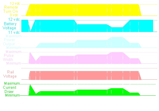
Power Supply Timing Chart:
The following diagram is a
timing chart and is one of the best tools to show
how multiple things relate to one-another. This
chart shows how various parts of an amplifier
with a regulated power supply relate to each
other.
At this point, you can
see that the remote is switched on and
the amplifier 'comes to life'.
At point B, you can see
a few things happen:
The current
draw peaks as the amplifier
charges the rail capacitors.
The battery
voltage drops during the current
surge. You might notice your
lights in your car dim when you
turn your amplifiers on.
The rail
voltage goes from minimum to
maximum. Remember that this is a
regulated power supply.
The pulse width
goes from minimum to maximum.
This is because the amplifier is
doing its best to get the rail
voltage to its target voltage as
quickly as possible.
At this point you can
see:
The current
draw goes back down as the rail
caps are now charged.
The battery
voltage stabilizes because the
amp is pulling less current.
The rail
voltage has stabilized.
The pulse width
goes back towards minimum because
the rail voltage is at its target
voltage.
At point D, an audio
signal starts to play and...
The current
draw increases slightly as the
amplifier drives the speakers.
The pulse width
increases slightly to keep the
rail voltage at its target
voltage.
At this point, the
power output starts to increase and...
The pulse width
starts to ramp up.
The current
draw starts to increase.
At point F' the audio
output levels off and so do the pulse
width and the current draw
At this point, the
power output, again, starts to increase
and...
The pulse width
starts to ramp up to maintain
rail voltage.
The current
draw increases until the current
demand levels off.
At this point, all
demand has levelled off. You should
notice how the battery voltage dropped
when current demand increased. If the
alternator was charging, the voltage
wouldn't drop (except for the short
period of time it takes for the voltage
regulator to react).
As the audio output
starts to fall (the volume of the test
tone is reduced)...
The battery
voltage starts to recover.
The pulse width
starts decrease.
The current
draw starts to decrease.
At point J, everything
levels off.
The amplifier's remote
power source is switched off and...
The power
supply shuts down by reducing the
pulse width to nothing.
The rail
voltage falls because the
switching power supply is no
longer operating.
The audio is
muted and reduced to silence.
Even if there were no muting
circuit, the audio would still be
reduced to nothing because there
is no rail voltage.
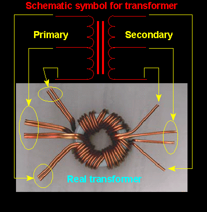
The diagram below shows the
relation between the parts of the schematic
diagram symbol and a real life transformer. Note
the double primary windings. These are used to
handle higher current without overheating.
If you find a problem
with this page or feel that some part of it needs
clarification, E-mail
me.