Please
'Boom' Responsibly As
most of you have noticed, the noise ordinances have
become much tougher lately. Most of this is due to
idiots, yes IDIOTS, who drive through residential areas
with their windows down while their system is playing at
full power. To make things worse, the music they listen
to has all sorts of foul language that's not suitable for
small children, (who may be playing outside). There are
even a few people, who are even beyond idiot status, that
play their systems at full power through residential
areas after 10:00 PM (when many people go to bed). I
don't believe that this type of behavior is good for the
industry. If the fines get too stiff, people will stop
buying large systems. If this happens, more people will
get out of car audio (who wants a mediocre system).
People get interested in things because they're exciting.
A deck and four 6.5" speakers are not going to
interest many of the younger car audio enthusiasts. If
car audio enthusiasts keep annoying more and more people,
the fines will keep getting tougher. All of this will
only reduce interest in the equipment that fuels the
industry. If you want to listen to your system at full
volume, get out on the highway where there's little
chance of bothering anyone. When you get to a red light,
turn it down. If the only thing attractive about you is
your 'system', you have some work to do. Bottom line...
Think about what you're doing. Think about other people.
It's not the end of the world if you have to turn the
volume down for a little while.
Speakers:
A speaker converts electrical
energy to mechanical/acoustical energy. It uses a
coil of wire, which acts as an electromagnet, set
inside of a magnetic gap of a permanent magnet.
The following demo shows the main components of a
woofer. Holding your cursor over the individual
buttons will highlight the respective component.
Clicking on the button will bring up a brief
description.
Voice coil motivation:
When a current is passed
through the coil of wire, called the voice coil,
it generates a magnetic field. This electromagnet
interacts with the field in the magnetic gap and
the voice coil moves. The direction of movement
depends on the direction of current flow through
the VC. Since audio is an AC waveform, current
flows in one direction and then changes polarity,
the VC moves either forward or backward from its
point of rest. The diagram below shows how the VC
is connected to the cone of the speaker. The cone
is the part of the speaker that actually makes
the sound by alternately creating an area of high
and then low air pressure.
Magnitude of cone movement:
When an amplifier drives a
speaker, it is driving the speaker terminals with
AC voltage. If the volume is at its minimum
position, the speaker doesn't move. If the
driving voltage is low, the speaker moves a
little. As the voltage increases (when you turn
up the volume), the cone moves further from it's
point of rest. Higher power amplifiers can drive
the speaker with higher voltage and therefore
produce more SPL (volume).
The following demo shows how
the magnitude of cone movement increases when the
volume is increased (and a higher voltage signal
is driven into the speaker). Click on the slider
handle to lock and unlock the handle. Move the
mouse left or right over the white bar to change
the volume level.
The next
diagram shows a detailed view of the voice coil
and the magnetic gap.
Please note that speakers DO
NOT produce power. A speaker
rated at 1000 watts is not necessarily going to
be more efficient than a speaker rated at 50
watts. If they are manufactured by the same
company (so that they are rated by the same
standards), the speaker rated to handle higher
power will be able to produce more sound pressure
level because it can be driven with a more
powerful amplifier without fear of damage. Many
times, a manufacturers cheapest woofers will be
more efficient and may be a better choice for a
low powered system.
Coaxials and Triaxials:
It is very difficult (read
impossible) to build a single driver capable of
accurately and efficiently reproducing the entire
audio spectrum. It is much easier to use multiple
drivers, each reproducing its own narrow band of
frequencies. Coaxial speakers are 2-way speakers
which employ a larger driver (for bass and
midrange) and a tweeter (for reproducing upper
midrange and treble). A triaxial speaker is a
3-way speaker with a woofer, a midrange and a
tweeter. Both types of speakers usually include
the required crossover components for the
midrange and high frequency drivers. The diagram
below shows a 3-way design and a graphical
representation of the frequency response
reproduced by each driver.
This diagram shows how the
voice coil position relates to input voltage. You
can see that the voice coil moves above the point
of rest when the voltage is positive. When the
voltage is negative, the voice coil is below its
point of rest. When the voltage is at 0 volts
(ground), the speaker is at its point of rest.
You should also notice that the magnitude of
displacement is directly related to magnitude of
the input voltage. More voltage means more
displacement. Higher power amplifiers can
generate more voltage at their speaker terminals.
Thiele/Small Parameters (not
all):
SD:
Effective piston area of the
cone. It will vary slightly from one 10 inch (or
any other size) to another but does not vary
enough to make a difference in the performance of
the driver.
Xmax:
By definition it is the peak
linear travel of a driver. If you measure the
distance that the voice coil can travel in the
gap (in one direction) while the number of turns
in the gap doesn't change, you have the Xmax. If
you go past this point, the actual windings in
the voice coil start to leave the gap. The
diagram below shows the voice coil at its maximum
travel at point of max linear travel and just
past its point of max linear travel.
BL:
BL is determined by the flux
density (B) in the magnetic gap and the length
(L) of voice coil wire in the gap. A higher BL
will generally mean a speaker will have a higher
relative sensitivity (efficiency). This doesn't
necessarily mean that all speakers with a higher
BL will produce a higher SPL. Often speakers with
very high BLs have a smaller Xmax.
The diagram below shows two
different motors (that's what they're called).
Motor 'a' is what you might find in a speaker
with a relatively low power rating and a
relatively short Xmax but its efficiency will be
relatively high. Motor 'b' will have a higher
Xmax, higher power handling due to the larger
voice coil windings and a lower efficiency. The
difference in the xmax is due to the difference
in overall length of the voice coil. Xmax=voice
coil length minus the gap height. The difference
in efficiency is due to a different number of
windings in the gap. Remember that the voice coil
is an electromagnet. The current passing through
the coil generates a magnetic field which is
distributed along its length. On the shorter
voice coil, more of the generated field is in the
magnetic gap producing a slightly stronger motor
but with a shorter stroke.
'R E ':
This is the DC resistance of
the voice coil. It will be lower than the rated
impedance of the speaker. A 4 ohm speaker may
have a DC voice coil resistance of 3.3-3.8 ohms.
Resonance:
'fs':
Free air (not in an enclosure)
resonance of the driver. All speakers have a
resonant frequency. At this frequency, the
impedance increases significantly.
'fc':
This is the resonant frequency
in a sealed enclosure. The resonant frequency
will tend to be higher but the impedance will not
go as high.
'no':
This is the reference
efficiency. It is usually expressed as xdB when
driven by one watt and measured at a distance of
one meter. Ex: 89dB/1w/1m. See note below for
more information related to reference efficiency.
Note below:)
You have to be careful when
looking at reference efficiency (sensitivity).
You can make a speaker really efficient by
designing the voice coil to fit entirely in the
magnetic gap. This would likely yield a
sensitivity of 104 or so. This speaker may work
very well if powered by a low powered amplifier
because of the high efficiency but would not be
able to produce high SPL at low frequencies
because it would have a very small xmax.
Actually, if the voice coil length was the same
as the height of the magnetic gap, it would have
no (zero) xmax.
You can also design speakers
for very high power handling and high SPL but
those speakers would likely have a very low
reference efficiency. Speakers designed for high
SPL in cars generally have a larger xmax and
therefore lower reference efficiency but would
easily out perform the speaker (in the previous
example) with the higher reference efficiency at
low frequencies.
Speakers that are designed to
operate in very small enclosures are usually less
efficient than speakers designed for larger
enclosures. To make the speaker perform in a
small enclosure, the suspension has to be stiff.
This will raise the resonant frequency. To get a
lower resonant frequency, they must add mass to
the cone of the speaker. This added mass and the
stiff suspension kill the efficiency.
The diagram below is a pitiful
graph which shows how impedance relates to
frequency.
The following demo shows how
the speakers act when testing them with a
battery. When you press the buttons, the battery
connection is made and the speakers move in the
direction dictated by their wiring.
NOTE:
I've heard about
at least one speaker manufacturer that makes
their drivers with the polarity opposite of the
above diagram. It is a company that makes drivers
for use in commercial PA cabinets, so you won't
likely see them in cars. I just wanted to make
this note to prevent excessive email from a few
smart @$$3$ out there. :)
Rated Efficiency:
Since there are nearly infinite
number of ways to measure the efficiency of a
speaker, many manufacturers will use the method
that gives the highest efficiency for their
speakers. To give a more accurate comparison of
speakers of equal size, you can enter the
Thiele/Small parameters into the following
calculator. Vas is in cubic feet. The fields
which contain 'speaker#1' and 'speaker#2' can be
used to enter the model number of diffferent
speakers. They have no bearing on the
calculations. They are simply there so that it's
easier to remember what speaker the specs are
for.
The following calculations give
only a VERY rough estimate. The output SPL WILL NOT be precise (for those who can not
understand this, I'm sorry). It is here to help
newbies understand how adding speakers or changes
in power affect SPL.
It assumes:
• The speakers are not being driven
beyond Xmax
• All of the speakers being used are
the same type and size
• All of the speakers are in the same
type and size enclosures
• The power is true RMS power
• The frequency response of your
subwoofer system (in the vehicle) is flat
• The reference efficiency is at 1
watt in an anechoic chamber
• You'll notice that there is no
choice for the woofer size. The efficiency of
some 10' woofers will be higher than some
12" woofers (and vice-versa). Refer to the
speaker's spec sheet for its reference
efficiency.
• If you apply more than their max
rated power to the speakers, the speakers would
be driven beyond x-max and the results will be
completely meaningless.
Find GUESTIMATED SPL output from
your system.
Input
Section:
Single
cab pickup with speakers behind seat
Car
with speakers in trunk and back seat folded up
Car
with speakers in trunk and back seat folded down
Car
with hatch back
Reference Efficiency? =
Decibels
Total Power? =
Watts
Total Number of Woofers? =
Output Section:
Gain From Multiple Woofers =
Decibels
Reference Power =
Watt
Gain Due To Power =
Decibels
Cabin Gain =
Decibels
Output Guestimation =
Decibels
First...
This calculator is not
designed to be 100% accurate (I don't know how
many times I have to say/type this). It's just
there to show how the SPL increases or decreases
with changes in the system.
For
clarification of output data:
Gain from multiple
woofers
tells how much of a change in SPL you use
different numbers of woofers.
Reference power
is the power that the manufacturer used
when they measured or calculated
efficiency.
Gain from power
is the gain in SPL you get from
increasing the power above the 1 watt
reference. doubling the power will give
you a 3 dB gain if all else remains
constant.
Cabin gain
is the reinforcement you get from your
vehicle's enterior. The values I chose
are from my experience. They certainly
won't be accurate for all vehicles.
What
you should realize after using the calulator
is...
*If
you manually enter a cabin gain of zero, and a
power output of 1 watt and enter 1 in the
'woofers' field, the output will equal the
reference output.
*If
you double the power to 2 watts, you gain 3dB.
*If
you set the power back to 1 watt but double the
cone area (number of woofers), you still gain
3dB.
*If
you double the power to 2 watts and use 2
woofers, you'd get 6dB gain over the reference
efficiency of a single woofer.
Note:
If
'cabin gain' is set to '0', the speaker output is
what you'd expect if the woofer were in its
enclosure in the middle of a large open space
with no reflective surfaces. Your car isn't a big
open space and it reinforces the overall output
of the system. In the vehicle, the cabin gain
will vary with the vehicle (which I guestimated
for various vehicles) and will vary with the
frequency (which I don't use in the calculations
at all). Like I mentioned before, this is not going
to be 100% accurate but... if you had a single
woofer in your vehicle and drove the speaker with
a 1 watt low frequency signal, this calculator
could help you predict how your output would
change if you added more speakers or power. The
cabin gain would be the difference between the
reference given by the manufacturer and the SPL
that you'd actually produce at 1 watt in your
vehicle.
I
get a fair amount of email concerning torn or
punctured surrounds. Most are from the
screwdriver or drill slipping when pressure is
applied to the screw head. There are a couple of
things that can help prevent or lessen the chance
that this will happen. First, use a bit that fits
the screw head well. Don't use a worn bit. A good
fitting bit will not have any 'slack' when
inserted into the screw head. I use bits that
have teeth on the sites of the bit to help grip
the inside of the screw head. You'll have to find
a bit that works well with the screws that you're
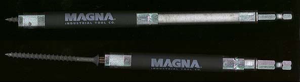
using. Second, use a bit holder that has a
sliding sleeve to help prevent the screw from
separating from the bit. When starting the screw,
the sleeve will be slid over the bit and screw as
is shown in the top example. As the screw grabs
the wood and starts to dig in, the sleeve slides
up out of the way to allow you fully tighten the
screw. Since the damage is usually done when
trying to start the screw in the wood, this
little tool will prevent almost 100% of the
accidents. I don't recommend using drywall screws
(as is shown below). I recommend using pan head
screws for most speakers.
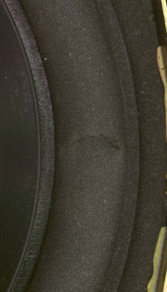
After
Damage has Been Done:
If
you have already damaged the surround, it can be
repaired with little or no change in performance.
Everyone has an adhesive of choice. I prefer
contact cement for this job. It can be applied in
a very thin layer and remains very flexible. The
following images are a before and after of the
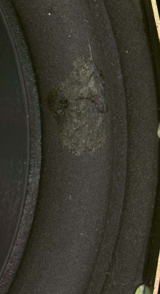
repair. When applying the adhesive, I use a
cotton swab that I've cut the cotton off of. You
can use anything that will allow you to get the
adhesive into the repair site. You want to apply
the adhesive to both sides of the damaged edge of
the surround. Generally, coating the applicator
and simply inserting it into the tear will assure
proper application of the adhesive. After the
adhesive is applied, realign the foam to where
you want it. You need to work fairly quickly
because the adhesive will start to set up in a
minute or so. Allow a couple of hours before
playing it at full power. If you apply the
adhesive properly and get the surround back
together as it should be, the speaker will be as
good as new. I've never had one fail after being
repaired. The repair below does not look very
strong but I could not pull the repaired area
apart after the adhesive set.
Before (above)
After (above)
WARNING: Turn your
sound card's volume to near its lowest position before
clicking on the link below.
This link is a 250hz
tone recorded at -1dBfs for 1 second and then it drops to
-2dBfs for 1 second. It repeats 3 times. This was put
here to give you a reference for the calculator above.
Most people don't know what a 1dB difference sounds like.
The following image shows how bottom
and top mount measurements differ.
If you
find a problem with this page or feel that some part of
it needs clarification, E-mail me.