Please
'Boom' Responsibly As
most of you have noticed, the noise ordinances have
become much tougher lately. Most of this is due to
idiots, yes IDIOTS, who drive through residential areas
with their windows down while their system is playing at
full power. To make things worse, the music they listen
to has all sorts of foul language that's not suitable for
small children, (who may be playing outside). There are
even a few people, who are even beyond idiot status, that
play their systems at full power through residential
areas after 10:00 PM (when many people go to bed). I
don't believe that this type of behavior is good for the
industry. If the fines get too stiff, people will stop
buying large systems. If this happens, more people will
get out of car audio (who wants a mediocre system).
People get interested in things because they're exciting.
A deck and four 6.5" speakers are not going to
interest many of the younger car audio enthusiasts. If
car audio enthusiasts keep annoying more and more people,
the fines will keep getting tougher. All of this will
only reduce interest in the equipment that fuels the
industry. If you want to listen to your system at full
volume, get out on the highway where there's little
chance of bothering anyone. When you get to a red light,
turn it down. If the only thing attractive about you is
your 'system', you have some work to do. Bottom line...
Think about what you're doing. Think about other people.
It's not the end of the world if you have to turn the
volume down for a little while.
Relay Basics:
A relay is used to isolate one
electrical circuit from another. It allows a low
current control
circuit to make or break an electrically
isolatedhigh
current circuit
path. One example where a relay is useful in car
audio is in the power antenna or remote output of
a head unit. We already said that the average
remote lead can only handle about one half of an
amp of current. If a circuit with a large amount
of current must be controlled by the remote
output lead of a head unit, a relay could be used
to buffer the remote output from the head unit.
The basic relay consists of a coil and a set of
contacts. The most common relay coil is a length
of magnet wire wrapped around a metal core. When
voltage is applied to the coil, current passes
through the wire and creates a magnetic field.
This magnetic field pulls the contacts together
and holds them there until the current flow in
the coil has stopped. The diagram below shows the
parts of a simple relay.
Relay Demo:
Drag your mouse over the
picture below. You'll see how the relay closes to
allow current to flow through the bottom lamp
when the coil is connected to the power source.
You can see how current flows through either set
of contacts depending on the position of the
movable contact. If you have a slow connection,
you may have to hold your mouse over the image
until it loads completely. Since this page has a
LOT of graphics, this will work best if you let
the page load completely before using this demo.
Clicking on the picture will bring the image to
the top of the frame.
The table below
shows just a fraction of the
available relay configurations.
This is a Single Pole Single Throw relay.
Current will only flow through the contacts when the
relay coil is energized.
This is a Single Pole Double Throw relay.
Current will flow between the movable contact and one
fixed contact when the coil is DEenergized and between
the movable contact and the alternate fixed contact when
the relay coil is energized. The most commonly used relay
in car audio, the Bosch relay, is a SPDT relay.
This is a Double Pole Single Throw relay.
When the relay coil is energized, two separate and
electrically isolated sets of contacts are pulled down to
make contact with their stationary counterparts. There is
no complete circuit path when the relay is DEenergized.
This relay is a Double Pole Double Throw relay.
It operates like the SPDT relay but has twice as many
contacts. There are two completely isolated sets of
contacts.
Yep! You guessed it. This is a 4 Pole Double Throw relay.
It operates like the SPDT relay but it has 4 sets of
isolated contacts.
Relay Specifications:
There are two specifications
that you must consider when selecting a relay for
use in an automobile, the coil voltage and the
current carrying capability of contacts. The coil
voltage for relays used in automobiles is ~12
volts. This means that if you apply 12 volts to
the coil, it will pull in and stay there until
the applied voltage is removed from the coil. The
current rating on relay contacts tells how much
current can be passed through the contacts
without damage to the contacts. Some relays have
different current ratings for the NC contacts
(which are held together by spring tension) and
the NO contacts (which are held together by the
electromagnet). If you need to pass significant
current through the NC contacts, you may want to
check the manufacturers specifications for the
relay.
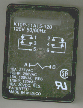
The relay pictured above has a
coil designed to accept 120 VAC at 50 to 60hz. If
you look at the specifications on the relay cover
below, you will see that the coil was designed to
operate on 120 volts A.C. There are relays
designed for use with 5vdc, 12vdc, 12vac, 24vdc,
24vac. Make sure that you check the relay's
specifications when using a relay that you're not
familiar with.
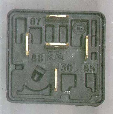
The Famous
Bosch Relay
Bottom View:
The most commonly used relay in
car audio and security is the Bosch relay. The
picture below is the bottom of a Bosch relay.
Take note of the markings (85, 86, 87, 87a, &
30) near the terminals.
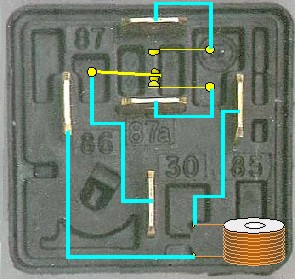
Internal Workings of Bosch
relay:
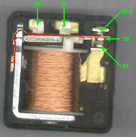
The following diagram shows
what those external terminals are connected to on
the inside of the relay. When there is no
difference of potential (voltage) across
terminals 85 and 86 (the coil), the relay's
movable contact (connected to terminal 30) is
held, by spring tension, against the electrical
contact which is connected to terminal 87a (the
normally closed contact). In other words, when no
voltage is applied the the relay coil, terminal
87a is connected to terminal 30. When 12 volts is
applied to the relay coil (terminals 85 and 86),
the movable contact (connected to terminal 30) is
pulled down/in by the electromagnet (coil) so
that it physically contacts the electrical
contact which is connected to terminal 87. Again,
in other words, if battery voltage is
applied to the relay
coil (terminals 85 and 86) terminal 30 will be connected to terminal 87. The red dashed line shows the path
in which electrical current flows from/through
terminal 30 to the contact of terminal 87a when the relay coil is NOT energized.
Remember that the relay coil
has to have a difference of potential between
terminals 85 and 86 in order for the coil to pull
the armature in/down. This means that you may
apply battery voltage to either terminal 85 OR 86
and then ground the OTHER terminal. The positive
battery voltage OR the ground connection may be
broken to make relay switch terminals (87 to
87a).
This flash demo should help you
understand how current flows through the relay as
the coil is energized and deenergized. Click HERE to make the demo fill this window.
Anytime that a relay coil is
driven by a circuit that is not specifically
designed to drive a relay, you should use a
quenching/suppression diode connected in parallel
with the relay coil. The diagram below will show
the connection of the diode. Initially, you may
think the diode
serves no purpose because the voltage applied to
the relay cannot pass through the diode. This is
true when the relay is energized. The diode comes into play when the
power source is removed
from the relay coil. When power is applied to the
relay coil, a magnetic field is created and
energy is stored in the coil. When power is
removed, the magnetic field collapses causing a
reverse voltage to be generated (it's called
inductive kickback or back EMF). The back EMF can
easily reach 200 volts. The diode will absorb the
reverse voltage spike. This voltage, if not
absorbed by the diode, will cause premature
failure of switch contacts and may cause the
failure of power switching transistors. You can
use virtually any type of rectifier or switching
diode (i.e. 1N4001, 1N4002, 1N400x... or Radio
Shack part #s 276-1101, 276-1102, 276-1103,
276-1104).
Voltage Graphs:
The following diagram shows 2
different voltage graphs. The top graph shows how
the parallel diode quenches the reverse voltage.
The bottom graph shows the unsuppressed voltage.
This voltage can damage low voltage transistors
and switches. You can right click on the diagram
to zoom in on the graphs.
Note:
Earlier I said that you
energize the relay by applying positive voltage
to either 85 OR 86 and grounding the remaining
terminal. The only thing that changes when using
the quenching diode is the fact that the positive
terminal and the striped end of the diode must be
together. If the
positive control lead is connected to the diode's
anode (unstriped end of diode). There will
effectively be a short circuit to ground possibly
causing damage to the control circuit (if the
control circuit is not properly fused). A 1 amp fuse will carry more
than enough current to energize the relay's coil.
Relays with Internal
Suppression Circuits:
There are some relays with
internal suppression circuits which make the
external diode unnecessary. The suppression
circuit is generally a resistor or a diode
parallel to the relay coil. The relays with a
diode suppressor will have polarity sensitive
coil connections. This means that the proper
relay coil terminal (the positive terminal) must
have the positive voltage applied to it. If the
relay is connected improperly, the relay may be
damaged or in some cases it simply won't operate.
Pull in Voltage:
The pull in voltage is the
minimum voltage required for the relay coil to
pull the contacts (30 and 87 on the Bosch relay)
together. The pull in voltage is about 8 volts
for a typical Bosch relay.
Drop out Voltage:
The drop out voltage is the
voltage at which the energized coil will release
the movable contact. The drop out voltage is
somewhere between 1 and 5 volts for a bosch
relay.
Coil Resistance:
In a DC relay coil, the coil resistance
determines the current flow through the coil. The
current draw by the coil of a bosch relay is
~0.160 amps (~75 ohm coil). In an AC relay coil, the resistance does not
solely determine the current flow through the
coil because the coil has inductance. The
inductive reactance along with the DC resistance work
together to limit the current flow through the
coil.
Remote Input Current:
The remote input current for
amplifiers varies with the amplifier and the
model. Some draw minimal current. Others draw a
little more. The upper limit of a properly
functioning amplifier is approximately 50ma (0.05
amps). If you're using/controlling more than 2
amplifiers, it is (in my opinion) much better to
use a relay to control the amplifiers. Actually I
really prefer having a relay in the remote
circuit (no matter how many amplifiers I'm using)
because it protects the head unit's remote output
circuit in case of a short circuit. The following
chart shows the remote input current for various
amplifiers I had laying around the shop.
Manufacturer
Model
Current Draw (mA)
MTX
2300
14
Jensen
LXA300
43
Pioneer
GMX602
1.5
Autotek
7150
16
Punch
200x2
14-45†
Autotek
200x1
17
Coustic
Amp162µ
22
Orion
275SX
28
Crossfire
CFA1000D
5
Lanzar
Vibe 250
17
Test conditions: 14.3vdc; Fluke
model 27 DMM; The meter was inserted in the remote supply
line.
†Punch amplifiers may draw slightly
more current when the power supply fuse blows.
This generally causes no problem because the
increase in current is still below the current
normally drawn by other amplifiers.
Note:
There is at least one very
popular brand of amplifier that draws as much as
500ma of current when the amplifier fails. This
is enough to damage the remote output switching
transistor in the head unit if the fuse is
missing or is of the wrong value. A relay in the
remote circuit will completely eliminate the
possibility of damaging the head unit in this
situation.
It's been mentioned quite a few
times that the Bosch relay's coil has a fairly
low resistance (~75 ohms). It has also been
suggested that you could use a different relay
with significantly more coil resistance so that
you draw less current from the remote output of
the head unit. The relay below is from Radio
Shack. Its stock number is 275-248. It has a coil
resistance of ~400 ohms which means that it will
draw ~1/5 the amount of current of the Bosch
relay. In the following image, the red wire is
the fused power source (10A max - even less for
small wire like I've used). The blue wire is the
remote from the head unit. The black wire goes to
ground. The green wire goes to the remote input
of the amplifiers and to fans if you have them.
Online Source for Relays:
Parts Express has a few relays that are suitable
for use in car audio applications. The following
is a direct link to the relay page.
The following calculator helps
you to select the wire size and fuses when using
a relay.
The default current
draw values are a good starting point. If
you know the exact values for your
equipment, enter them in the appropriate
fields.
The smallest
recommended wire size is 16g. You could
use smaller wire but smaller wire is not
as easy to crimp reliably which will lead
to unreliable connections.
If you are using the
relay for fans alone, enter 0 (zero) in
all other current draw fields.
The distribution block
shown is a relatively low current type
(like the type used in marine
applications).
The wire from the
dblock to the amp is the remote lead. The
battery and ground connections for the
amplifier are not shown to reduce
clutter.
Click HERE
to make the calculator fill this window.
A relay can be wired so that it
will operate when the ground connection is made/broken (instead
of when the 12 volt connection is made/broken).
The diagram below shows the connection. Remember
that it doesn't matter which connection (power or
ground) is made or broken as long as the circuit
driving the relay coil is made/broken. Click the
switch position selector to toggle the switch.
REASON:
If the switch has to be a
significant distance from the relay (and you put
the switch in the 12 volt source wire), the 12
volt source wire will have to run a long way
also. If this wire happens to get shorted, it
will keep blowing fuses and the short circuit may
be hard to find. If you switch the ground
connection, the worst case scenario is that the
relay will turn on when the wire becomes shorted
to ground. This will also make it much easier to
find the shorted part of the wire and you won't
blow any fuses.
Relay Terminal Connection:
When switching power with a
bosch type relay, if the situation allows, apply
power to terminal 87 and use terminal 30 for the
output terminal.
REASON:
If the relay is wired so that
terminal 30 is the input and terminal 87 is the
output, the circuit will work exactly as the
previous example but when the relay is switched
off, terminal 87a will become energized. Terminal
87a could be insulated to prevent any problems
but wiring it as shown in all of the diagrams
will prevent any additional problems.
You should remember:
Relays electrically isolate the control circuit from the
circuit being controlled.
Relays allow a small amount of current to control a large
amount of current flowing in a separate circuit.
A diode should be connected across the relay coil to
prevent a large voltage spike when the voltage source is
removed from the coil.
If you find a problem
with this page or feel that some part of it needs
clarification, E-mail
me.