![]()
Please 'Boom' Responsibly As most of you have noticed, the noise ordinances have become much tougher lately. Most of this is due to idiots, yes IDIOTS, who drive through residential areas with their windows down while their system is playing at full power. To make things worse, the music they listen to has all sorts of foul language that's not suitable for small children, (who may be playing outside). There are even a few people, who are even beyond idiot status, that play their systems at full power through residential areas after 10:00 PM (when many people go to bed). I don't believe that this type of behavior is good for the industry. If the fines get too stiff, people will stop buying large systems. If this happens, more people will get out of car audio (who wants a mediocre system). People get interested in things because they're exciting. A deck and four 6.5" speakers are not going to interest many of the younger car audio enthusiasts. If car audio enthusiasts keep annoying more and more people, the fines will keep getting tougher. All of this will only reduce interest in the equipment that fuels the industry. If you want to listen to your system at full volume, get out on the highway where there's little chance of bothering anyone. When you get to a red light, turn it down. If the only thing attractive about you is your 'system', you have some work to do. Bottom line... Think about what you're doing. Think about other people. It's not the end of the world if you have to turn the volume down for a little while. |
| Airbag
Warning: A
test light can (read: will) set off a supplemental
restraint system if the wrong wires are probed. These
wires are generally (but NOT always) marked with yellow
loom or tape. If you probe one of these wires (which may
be in virtually ANY factory wiring harness anywhere in
the vehicle), and set off a single airbag, you may easily
cause THOUSANDS of dollars in damage. If you hit the
wrong sensor wire and trigger ALL of the airbags, there
may be enough damage that the vehicle may be totalled
from the cost to replace the bags and the affected trim
panels. Some airbag systems destroy the entire dash, the
door panels and even parts of the seats when they deploy.
This page shows how to use a test light to test for blown
fuses in the aftermarket audio system that you installed
(or are going to install). If someone asks you to work on
a car with airbags, and you don't know what you're doing,
DON'T do the install. If you're going to install a system
in your vehicle and are going to be
probing wires of which you don't know their precise
function, use a multi-meter to find the appropriate wire.
As a final note, disconnecting the battery in the vehicle
does not necessarily remove the chance of the SRS
deploying. Some systems have backup supplies which are
designed to allow the system to work properly even if the
battery is destroyed in the accident. USING A TEST LIGHT A test light is, when properly and appropriately used, one of the best and quickest pieces of test equipment available for troubleshooting 12 volt power systems. CONNECTIONS The test light will light when there is a sufficient difference of potential between the point of the light and the alligator clip on the other end of the ground wire. The following shows the equivalent between the reading on a digital multimeter and a test light. You can see that the wires that have 12-14.5 volts on them also light the test light. You can (and probably should) use a voltmeter for troubleshooting. If you do, the meter will read approximately 12-12.5 volts with the engine off and will read between 13.5 and 14.5 with the engine running. If you're not probing anything other than the wires going into the radio or the amplifier, the test light is safe. If you're testing the voltage in any other connector under the dash, you absolutely MUST use a digital multimeter. You'll notice the the meter grounds are connected to a shiny, bare piece of metal. This is also necessary for the test light but the test light's ground was omitted for clarity.
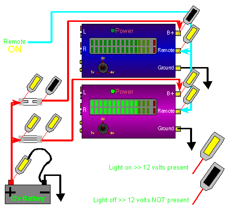
NOTE: In the following examples, the ground wires for the test lights were ommited for clarity. Test lights with light bulbs will not work without the ground wire being connected. EXAMPLES: Amplifiers: In the
lower right of the diagram below, you will see the legend
which shows which test light is on and which is off. You
will see that all connections to the battery side of the
fuses have 12 volts on them. You can also see that there
are 2 fuses. One of the fuses is blown. you can see that
the light on the amplifier side of the good fuse is lit and the light on the amp side of the
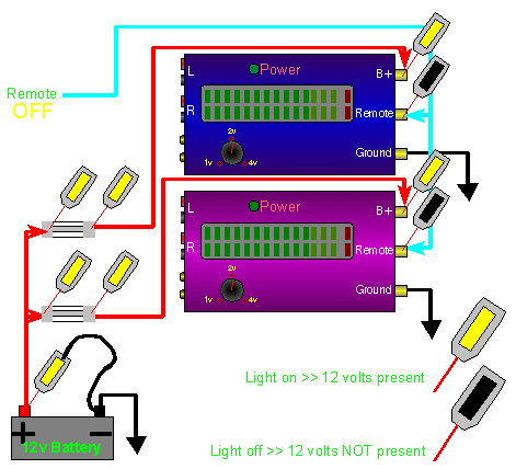
blown fuse is NOT lit. In the diagram below,
the remote output is off. Both amplifiers are off. Notice
that the test lights on the amplifiers' remote terminals
are not lit. The test lights on the battery terminals are
lit. These two examples should give you an idea of how to
troubleshoot with a test light. If you know which
terminals or wires should have power, you can use a test
light to quickly find many of the problems that you'll
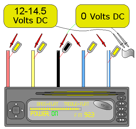
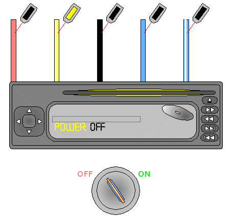
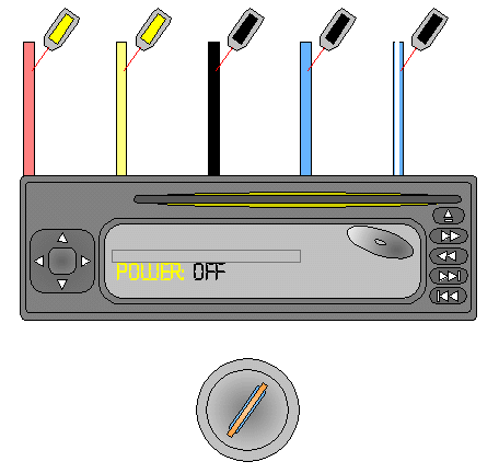
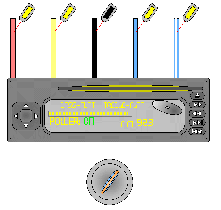
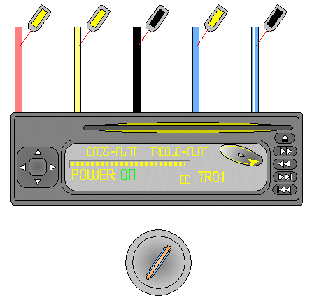
encounter. Note: Head Units: In the following diagrams, you'll see when voltage is present on each of the power and control wires. If you're new to car audio, read the head unit page for a better desription of the function of each wire connection. In this first diagram, you can see:
|
You should remember:
1.The indicator in an incandescent lamp based test light will
light when there is a sufficient difference of potential
(voltage) between the test light's probe and the test light's
ground clip.
2.The lamp in a test light can give you an indication of a low
voltage situation or a voltage drop in a circuit.
| If you find a problem
with this page or feel that some part of it needs
clarification, E-mail
me. This is a link to this site's home page. |