- Potentiometer:
- There are many instances where
only a portion of an output voltage from a signal
source is needed. If we allowed the full output
voltage from a home CD player to be driven into
the input of an amplifier, the amplifier would
play at or near full power at all times. This
would become quite annoying in a very short
period of time. To reduce the overall volume, we
need to allow only a fraction of the full signal
through to the amplifier. To control the level of
the signal, we use a potentiometer. A
potentiometer (also know as a 'pot') is a
modified resistor. Potentiometers can be used to
allow a change in the resistance in a circuit or
as a variable voltage divider (in the case of a
volume control). If you have a rotary volume
control on your TV or radio, it is (more than
likely) a potentiometer being used as a variable
voltage divider.* A potentiometer generally has 3
terminals. 2 of the terminals are connected to
the opposite ends of a resistive element. The 3rd
terminal (usually, is physically in-between the
other 2 terminals) is called the wiper. The wiper
is a contact (actually, generally many very small
contacts) that slides along the resistive
element. The diagram below shows the schematic
symbol for a pot.
- *If your volume control clicks and
steps the volume up or down with each click, it's
probably a rotary encoder (a switch), not a
potentiometer.
-
- The following diagram shows how
the schematic symbol relates to the drawing of
the potentiometer.

Voltage
Dividers
- A Potentiometer as a Variable
Voltage Divider:
- We covered voltage dividers on
the resistors page. A pot connected as it is in
the following diagram will act to divide the
voltage like the 2 individual resistors. In the
diagram below, you can see that the linear
taper‡ potentiometer is in the middle of
its range of travel. You can also see that 12
volts is applied to terminals 'A' and 'B' are
connected to the 12 volt battery. This means that
the output† from the slider will be 6 volts.
‡ This means that the resistance of
the resistive element increases in direct
proportion to the distance traveled along the
resistive element. In the middle of travel, the
resistance from the sliding terminal to either of
the other terminals is half of the total
resistance.
†The output
is simply the voltage at the point where the
wiper contacts the resistive element.
- Resistance Taper:
- In the previous paragraph, I
mentioned that the potentiometer had a 'linear'
taper. These are general purpose potentiometers
and may be used for controlling DC voltage (as it
did in the diagram) or to control the levels of
the individual bands on an equalizer. For volume
controls you need to use a potentiometer with a
'log' (short for logarithmic) taper. This is
because the human auditory system works
logarithmically. If we'd use a linear taper pot
for a volume control, the low end of the volume
control's range would be 'touchy'. What I mean to
say is that the volume would seem to increase
really fast at the bottom end of the VC's range
and would require a lot of travel at the upper
end of the VC's range. As you can see by the
graph below, the resistance of the linear pot
(red line) at 50% of its travel is 50% of its
resistance. The log pot's resistance is far less
than 50% at 50% of its travel. You have to go to
about 85% of its travel to reach the midpoint of
its resistance (500 ohms for a 1000 ohm pot).
- In the next diagram, you can
see that the slider has been moved toward the
positive terminal. This means that the output
voltage will be higher than 6 volts. In this case
the output voltage is 7.5 volts DC. If the slider
was moved closer to the negative terminal, the
voltage would be lower.
- Output with AC:
- If the pot was connected to an
AC signal generator (i.e. sine wave generator)
instead of a battery, the voltage on the output
terminal would be ~63% of the input voltage from
the generator. If the input signal was 12 volts
AC, the output would be 7.5 volts AC. The
following diagram shows the input and the output
voltages graphically with both AC and DC input
voltages. It is based on the same slider position
as was used in the previous diagram.
- Rotary Potentiometers:
- The following diagram shows a
rotary potentiometer at 50% and ~63% of its range
of travel. These positions would correspond to
the positions of the slider pot in the previous
diagram. This is a single turn potentiometer
which means that it can travel its entire range
within 1 complete revolution if its shaft (knob).
Actually, a single turn pot will only travel
through about 270º of a complete revolution.
There are other potentiometers that have some
sort of mechanism to increase the number of times
the shaft must be turned to travel through its
entire range of motion. This is generally done
with gears but I've seen it done in a planetary
gear configuration using ball bearings. The
multi-turn potentiometers are used to make it
easier to precisely set the output level.
- Power Ratings:
- Potentiometers have power
ratings just as resistors do. When the
potentiometer are used for preamp level audio and
such, power dissipation isn't really a problem.
If you are using the potentiometer to control a
signal with significant current flow, you'd have
to calculate the power dissipation across its
resistive element and use a potentiometer of a
sufficient power rating. Refer to the Ohm's Law page for the appropriate formula.
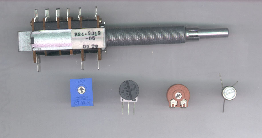
- In the picture below, at the
top is a multisection potentiometer used in older
head units. Below, various styles of printed
circuit board potentiometers.
- The diagram below shows how to
wire a volume control to be inserted into the
preamp line. If noise is a problem when you touch
the metal shaft, ground the metal part of the
pot. A potentiometer specifically designed for
use as a volume control (a pot with a
'logarithmic' taper) will give the most linear
volume control. The Radio Shack pt# 271-1732 is a
good choice.
Click HERE
to make the calculator fill this window.
|