|
Wiring a
3-Way or 4-Way Switch | ||||
Do you need to wire 2
switches to control the same light or lights??
Here are the instructions for wiring:
| ||||
Wiring a 4-Way Switch
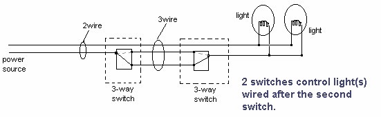
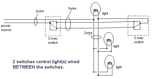
A 4-way switch is used when you need 3 or more switched to control the same fixture. I will show how to wire 3 switches, however you can add as many 4 way switches to the circuit as you need or want.For 4-way switch wiring, you will need two 3-way switches (one at each end) and then as many 4-way switches as you want in between. 2 wire cable runs from the light to the first switch, and then 3 wire is run between all the switches.
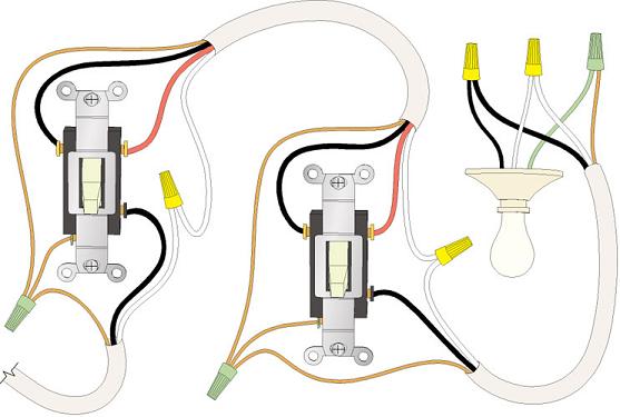
At the light, the black (hot) wire will pass right through going to the first switch. Attach it to the white wire of the wire running to the switch. The white wire from the power source will attach to the light's white wire. The light's black wire should be attached to the black wire running to the first switch.
At the first switch (a 3-way switch), the white wire (hot) coming from the light, will be connected to the dark colored screw. Color the end black with black paint or a black marker to indicate it is hot. The red and white wire of the 3-wire going to the next switch should be attached to the light colored screws. Connect the black wire of the 3 wire cable to the black coming into the switch from the light.
At each of the next switches except the last, use 4-way switches, attach the the red and white of the wire coming into the switch to the bottom of the switch's screws. Attach the red and white of the wire leading to the next switch to the screws at the top of the switch. Attach the two blacks together. At the last switch (a 3-way switch) attach the black wire to the dark screw and the white and red to the light colored screws.
Throughout the rest of this page the following terms will be used:The ground wire is not shown in any of the diagrams.
- Line This is were the power (HOT and NEUTRAL) is coming from.
- Switch Leg This is the write that comes from what ever is to be switched. It could be a switched outlet or an overhead light.
- Three-Way This is a switch that has three terminals (screws) on it, excluding the ground wire. It is used to switch a light from two different locations. This is the part that often confuses the novice ("Why is it called a three way if you only use two of them?") One of the terminals will be a different color than the rest. This is the 'point' or 'common'.
- Travelers On three-way switches they are the two like-colored terminals (screws). The wires that are connected to these terminals are referred to as the 'travelers'. In the diagrams below, the travelers will always be the RED and BLACK wires of a 14/3 cable.
- Point This is the third (usually black) colored terminal on a three-way switch.
- Four-Way This is a switch that has four terminals on it, excluding the ground wire. It is used between two three-way switches to control a light from a third (or more!) location.
- 14-3 This is a three conductor (14 gauge wire), excluding the ground wire, cable. The wire colors are almost always RED, BLACK and WHITE.
- 14-2 This is a two conductor (14 gauge wire), excluding the ground wire, cable. The wire colors are BLACK and WHITE.
Here is the key for the diagrams:
The standard method
Below is the method I was taught.
You may be wondering what makes a three-way switch work. If so you are not alone. What makes things work is the internals of the three way switch. When the switch is moved from one position to another, the internal connection switches to the other traveler terminal.In the diagram above you can see the labels Internal Connection. In the diagram below the second switch has been "thrown" which changed the internal connection to complete the circuit.
Follow the circuit from the black LINE side through the internal connection in the switches to the switch leg.
Different Configurations
Now the only other thing to consider is different configurations of where the switch leg and line come into the switches.The below diagram shows how to wire things up when both the switch leg and power come into the same box.
What may concern you in the above diagram is that black of the switch leg is connected to a white wire. This white wire will be live when the circuit is complete. A white wire caring line voltage is only "code" when is is being used in a switch situation. It is also the most common method to identify a switch leg (when you see a black and white connected one COULD be a switch leg).
Note that the 2000 NEC code now requires that this wire be marked (usually with black tape) as to "not confuse" people.
Note2: I received an email (09/2003) that stated that updates to the code require painting or marking with permanent marker the white wire when used in the above fashion.
The next case is when the Feed and switch leg all come into a separate box (for example a ceiling box for an overhead light).A switch leg (14/2) is run from that box to one of the three-way switches.
Four Way Switch
Now lets throw a four way switch into the picture.The terminals on the four way switch will be labeled to let you know which ones to connect to each leg of the travelers. The third (white) wire in the 14/3 is connected up as to just pass through.
What happens when the four way switch is flipped is the internal connections are reversed. That is, if, internally, S1's RED was connected to S2's RED and S1's BLACK went to S2's BLACK (as shown), switching the four way will cause S1's RED to go to S2's BLACK and S1's BLACK to S2's RED. That will either make or break the circuit (in the diagram, it will complete the circuit).