|
Time to Go to Work Step 1: The camshaft and timing set have been installed. Make
sure that the timing marks on both the cam gear and crank gear
are aligned properly per the cam installation instructions. Use chalk
or similar marker to better define the marks. Step 2: For example, we have our cam card and it suggests we
install the cam on 106 degree intake centerline. Install all the rock-
er arms and pushrods in the engine as normal. On #1 intake lobe,
install the solid lifter in place of the hydraulic lifter, if a solid
lifter
or roller cam is being checked, use the respective lifter. Adjust the
#1 intake lash to exactly zero. Do not pre-load on the lifter. Next,
adjust the #1 exhaust lash to zero. You should be able to turn both
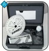
pushrods with your fingers easily. Step 3: Attach your COMP Cams
pointer (part #4194) to the block. Many
people will make a pointer out of some
sort of rigid, yet manageable wire. A stiff
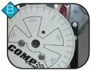
coat hanger wire works well (fig. B). Step 4: Attach the degree wheel to the balance and install the
assembly on the crankshaft. There are several ways to attach the
degree wheel to the crankshaft. In our example, the degree wheel
is mounted to the balancer. The crank may be rotated from either
the from or from the flywheel end. Obviously, if the engine is in the
car, you must rotate from the front. Remember, the greater the
leverage, the smoother the crank rotation, thus more accuracy.
NEVER use the starter to turn the engine while degreeing the cam. Step 5: Before installing the piston stop,
rotate the crankshaft to get the #1 piston in
approximate T.D.C. position with both the
intake and exhaust valves closed. This can be
a rough guess, but it can save you from mak-
ing a mistake later. Adjust your pointer to zero
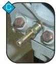
or T.D.C. on the degree wheel. Step 6. Turn the crankshaft opposite the
engine rotation approximately 15-20
degrees. This will lower the position
enough to allow the T.D.C. stop to be
installed in the spark plug hole. Screw in the
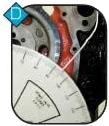
piston stop until it touches the piston, (fig. C). Continue to turn the engine in the same direc-
tion until the piston comes back up and touch-
es the piston stop. Mark the degree wheel
with a pen or pencil on the number the pointer
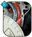
is on (fig. D.), Turn the engine in the other direc-
tion, same as engine rotation, until the pis-
ton comes back up and touches the piston
stop. Make a mark on the number the pointer
is on (fig. E). |
|
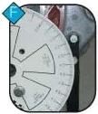
Step 7: Remove the piston stop after
marking the two points on your degree
wheel. Rotate the crankshaft to the midpoint
of the two marks. This point is T.D.C. for cylin-
der #1. Without rotating the crankshaft, adjust
the degree wheel to read 0 degrees at the
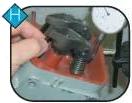
pointer (fig. F). Step 8: Attach the dial indicator to
the dial indicator mount. Position the dial
indicator mount so the tip will contact the
retainer of the #1 intake valve (fig. G). Step 9: Rotate the engine in the
normal direction of crankshaft rotation
until you reach maximum lift. The dial
indicator will change direction at the
point of maximum lift. At this point, set
the dial to zero (fig H). Step 10: Back the engine up (opposite normal rotation) until the
indicator reads .100". Turn the engine back in the normal
direction
of rotation until the dial indicator reads .050" before maximum
lift.
Record the degree wheel reading. Step 11. Continue to rotate the engine over in its normal
direction
of rotation until the indicator goes past zero to .050" on the
closing
side of maximum lift. Again, record the degree wheel reading. Step 12: Add the 2 numbers together and divide by 2. That num-
ber will be the location of maximum life of the intake lobe in rela-
tion to the crank and piston. This is the intake centerline. For
example: The first degree wheel reading was 96 degrees. The sec-
ond reading was 116 degrees. These 2 numbers (96 + 116) added
together will be 212. 212 divided by 2 will equal 106. Your actual
intake centerline is 106 degrees. Reference back to your cam spec
card and we see that the recommended intake centerline for your
camshaft is 106 degrees. Everything is where it should be. In the event that your camshaft did not degree in as per manu-
facturers specs, it will be necessary to either advance (move
ahead) or retard (move back) the cam to meet suggested intake
centerline. Depending on the engine application, there are several
different suggested methods for advancing or retarding the
camshaft. One common method is by use of a crank gear with multiple keyways-each one being at a slightly different relationship to the gear teeth. A 2nd method is to use offset bushings that fit on the cam pin and in the cam gear. The offset will advance or retard the cam depending on how the bushing is placed on the cam pin. Another method is by offset keys that fit into the crank gear key way. A more elaborate system uses an adjustable timing gear. Contact COMP cams or your local COMP Cams dealer for the method best suited to your application. NOTE: When degreeing a cam, remember to look at the degree wheel as a full 360 degrees no matter how the degree wheel youre using is marked. Many degree wheels are marked in 90 degree or 180 degree increments. On wheels that are marked in 90 degree increments, keep in mind that you must continue to count the number of degrees past 90 degrees. Be sure all readings are taken from Top Dead Center. Keep in mind that to advance the cam, you must lower the intake centerline. For example, if our cam has a lobe separation of 110 degrees, the cam is "straight up" when the intake centerline is 110 degrees. Moving the centerline to 106 degrees advances the cam 4 degrees. If we change the centerline to 112 degrees, this would be 2 degrees retarded.
| |||||||||||||||||||||||||||||||||||||||||||||||||
 You are now ready to
locate the
intake lobe centerline relative to T.D.C. If you
are not absolutely sure that your 0 degree mark is set at T.D.C.,
repeat this procedure. This step is critical to proper cam align-
ment.
You are now ready to
locate the
intake lobe centerline relative to T.D.C. If you
are not absolutely sure that your 0 degree mark is set at T.D.C.,
repeat this procedure. This step is critical to proper cam align-
ment.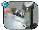 It
is important that the indicator plunger be
parallel to the valve stem. Any variance in
the angle of the indicator will introduce geometric errors into the
lift readings.
It
is important that the indicator plunger be
parallel to the valve stem. Any variance in
the angle of the indicator will introduce geometric errors into the
lift readings.