Please 'Boom' Responsibly As most of you have noticed, the noise ordinances have become much tougher lately. Most of this is due to idiots, yes IDIOTS, who drive through residential areas with their windows down while their system is playing at full power. To make things worse, the music they listen to has all sorts of foul language that's not suitable for small children, (who may be playing outside). There are even a few people, who are even beyond idiot status, that play their systems at full power through residential areas after 10:00 PM (when many people go to bed). I don't believe that this type of behavior is good for the industry. If the fines get too stiff, people will stop buying large systems. If this happens, more people will get out of car audio (who wants a mediocre system). People get interested in things because they're exciting. A deck and four 6.5" speakers are not going to interest many of the younger car audio enthusiasts. If car audio enthusiasts keep annoying more and more people, the fines will keep getting tougher. All of this will only reduce interest in the equipment that fuels the industry. If you want to listen to your system at full volume, get out on the highway where there's little chance of bothering anyone. When you get to a red light, turn it down. If the only thing attractive about you is your 'system', you have some work to do. Bottom line... Think about what you're doing. Think about other people. It's not the end of the world if you have to turn the volume down for a little while.


Bipolar Junction Transistors (BJTs):
This section will, in no way, tell you everything about transistors. It will just give you a general idea what transistors are and how they may be used in car audio. The two main types of transistors are bipolar transistors and field effect transistors.
A bipolar transistor uses a small current to control a larger current, a little like a relay. Bipolar transistors generally have 3 terminals. The control terminal is called the base. The other 2 terminals are known as the emitter and the collector and they carry virtually all of the current flowing through the transistor. There are 2 basic configurations of bipolar transistors, one is an 'NPN' the other is a 'PNP'. The two are very similar. The biggest difference is the direction of current flow through the collector and emitter. For now we will mainly discuss the NPN transistor.
Current Control:
OK, I said that a transistor is sorta like a relay. Remember that you have to have a certain amount of voltage across the coil of a relay for the relay to engage. A transistor needs to have a small amount of voltage difference between the base and the emitter. The required voltage is usually about .6 volts. On an NPN transistor, the base must have a positive voltage with respect to the emitter. Look at the diagram below. It shows the schematic symbol for an NPN bipolar transistor (left) and a PNP bipolar transistor. Note the names of the individual terminals.

NPN Bipolar transistor PNP Bipolar transistor


One problem faced by installers is the need to reliably switch a relay when the switching output from the control device is less than the 12 volts needed to actuate the relay. In the first diagram, you can see that the voltage applied to the resistor is 0v D.C. and the relay contacts are not closed. In the next diagram, you will see that 12 volts D.C. is applied to the resistor and the relay contacts are closed (because the transistor is now conducting current).

OFF ON

You no doubt noticed the resistor connected to the base of the transistor. This is to prevent damage to the transistor. If the voltage applied to the base is greater than approximately .6 volts (with respect to the emitter) the transistor may be damaged. Think of it like this... (I know my analogies ARE lame, but they will help some people) If you were turning a light switch on with the blade on the front of a bulldozer (don't try this at home, kids), you would have to be very precise in positioning the blade to prevent damaging the switch. If you connected the switch to the dozer blade with a rubber band, the dozer blade could still turn on the switch and the blade could go as high as physically possible without destroying the switch. Now, what if the rubber band is too strong or too weak? The switch might still be destroyed if the rubber band was too strong or, if the rubber band is too weak, the switch may not be switched 'on' at all (even at the highest position of the dozer blade). The same is true with the transistor. If a resistor with a low resistance is connected in series with the base and a high voltage is applied to the resistor, the transistor may still be destroyed. If the resistor has a very high resistance and a voltage is applied to it, the transistor may not be fully turned on. If a transistor is only partially turned on, it means that there will be a voltage drop between the collector and the emitter of the transistor and the transistor may become hot.
If a transistor is connected as shown in the previous diagram, there will be a voltage drop across it because the transistor cannot be turned 'on' enough to have absolutely no voltage across it while current is flowing through it. Since there is a voltage drop across the transistor and current flowing through it, there will be power dissipation in the form of heat. The amount of heat produced is determined by the power dissipation. If the transistor is not mounted to a heat sink, it may be destroyed by the heat.
Now, just for fun, push, pull or drag your mouse over the picture below. Watch the voltmeter and the relay's movable contact.


DESIGN PARAMETERS: This section will give some, but by no means all critical parameters.

BETA: One parameter tells you the amount of D.C. gain that the transistor will give you. It is generally called beta or hfe. If the transistor's beta is 150 and the transistor has 2 amps of current flowing through the collector and emitter, the current flowing through the base will be 2/150 or .013 amps of current.

CURRENT: Another critical spec is the current rating for the transistor. Please note that all given current ratings are for a transistor temperature of 25c or approximately 77 degrees farenheit. The 'safe' current carrying capabilities decrease significantly as the temperature rises. It is standard procedure to use a transistor rated for much higher current than will typically be required.

VOLTAGE: In most design situations, the maximum voltage which will be applied to the transistor is very critical. Too much voltage will damage a transistor as quickly as too much current. If you're using it to simply turn on a relay, it is not very critical. There are few transistors which cannot handle at least 15 volts between the emitter and the collector.

POWER DISSIPATION: Earlier we talked about power dissipation as it applies to transistors. Remember that any time there is a difference of potential (voltage) between the emitter and collector AND current flowing through the transistor, there will be power dissipation. And when you have power dissipation, heat 
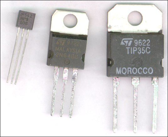
will be produced. Generally, the power rating for a transistor is determined by its case style. The picture below will show you a few case styles. Left to right, TO-92 case good for approximately .5 watts; TO-220 case, usually rated for 100-125 watts; TO-218 case, generally good for 150 watts. They are shown at 4 times actual size.

trancase.jpg

On these transistors, the terminals are: TO-92 EBC; TO-220 BCE; TO-218 BCE. B=base C=collector E=emitter


backward If you find a problem with this page or feel that some part of it needs clarification, E-mail me.

This is a link to this site's home page.

forward