This page will contain circuits that I've been asked to build.
DISCLAIMER:
All of these circuits have been tested but you use them
at your own risk.
Infrared Repeater
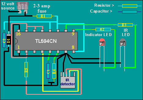
The red LED is the indicator LED. It tells you when the detector is picking up the signal. It also lets you know if the output of the repeater is working correctly. The darker LED is the IR LED. It must be placed in front of the device which is to be controlled by the repeater.
PARTS LIST
R1: 1 ohm 1/4 watt or higher
R2: 1000 ohms 1/4 watt or higher
R3: 750 ohms 1/2 watt
R4: 15,000 ohms (critical) 1/8 watt or higher
R5: 75 - 100 ohms 1/4 watt or higher
C1: 1000pf (.001uf) (critical) ceramic capacitor not recommended
C2: 330uf - 1000uf electrolytic Radio Shack pt #  272-957
IR detector: Radio Shack pt # 276-137
IC1: TL594CN Source Farnell Electronics www.farnell.com 1-800-718-1997
IR LED: Radio Shack pt # 276-143
D1: 1N4001 or better
Notes:
***Most Importantly, use a socket for the TL594. If you accidentally destroy the 594 when working with it, you would have to start over in most cases. With the socket, you can simply pop out the old chip and put in the new chip.
- R1 helps to filter the 12 volt signal. An inductor would work better but it would be more difficult to find any specific value.
- R2 limits the current flow in the led to approximately 12ma.
- R3 limits the current flow in the IR LED to approximately 16ma.
- R4 is the timing resistor for the TL594 and must be the proper value for the device to work.
- R5 is to protect the voltage regulator in the TL594CN.
- C1 Is the timing cap for the TL594.
- C2 is a filter capacitor to reduce the noise getting to the 594 and the IR detector.
- TL594 is a PWM IC that is commonly used for amplifier power supplies. It supplies the required 5 volts that the detector needs and converts the demodulated pulses from the the detector to 40,000hz pulses.
- These things are grounded:
- Pins 1,7 and 16 of the 594
- The negative lead of C2
- The anode (end without stripe) of D1
- The cathode (short leg) of both LEDs
- One end of R1 and C4
- The leg of the IR detector closest to the tab on the case. Check the schematic that comes with the detector to make sure that the one you get matches the one in my diagram. This is a picture of the detector that I got from RS. The black wire is ground, the red goes to the 5 volt regulator (pin 14 of the 594). The green wire goes to pin 4 of the 594.
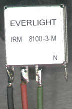
These things are connected together. You can check them with an ohm meter before powering it up for the first time.
- TL594, pins 2, 15, 14, 13 and one end of R5.
- TL594, pins 8, 11, 12, positive end of C2, and one end of R1.
- Striped end of D1, the other end of R1 and one terminal of the 3 amp fuse.
- Pin 9 and one end of R2.
- Pin 10 and one end of R3.
- Pin 14 on the 594 is the 5 volt regulator output.
- Pins 9 and 10 are the outputs for the LEDs. They go high when the chip is triggered.
- Pin 4 is being used for the input from the IR detector. The chip can be controlled by other pins but this is the easiest way.
Even more (somewhat) useless information
- Pins 5 and 6 are the timing pins for the 594. They determine the output frequency for the output on pins 9 and 10. The repeater has to have a 40,000hz output frequency for the IR receiver on the TV or VCR to be able to detect it.
- You should use heat shrink tubing on the IR LED's leads to prevent a short circuit.
- You should make sure that the signal from the repeater and the signal from the remote control can't be seen at the same time by the device that is being controlled. If both signals reach the device at the same time you will be blown to bits.... Well maybe not but the device won't work properly.
- All of the IR detectors that I've bought from RS have an intermittant pulse output with no input. This causes the indicator LED to blink at random intervals. You may not want the indicator LED mounted where you can see it. Especially if you drive very much after dark.
- The leads on C2 should be as short as possible and the capacitor should be mounted as close to the 594 as possible.
- D1 is to protect the IC and detector if the repeater is connected with reverse polarity.
Thermally controlled fan driver
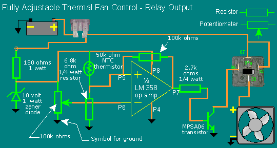
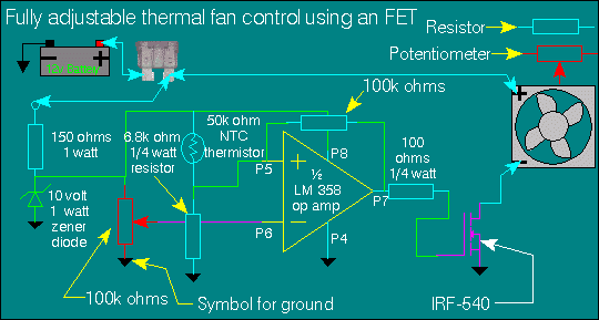
Possible supplier: Mouser electronics http://www.mouser.com
Parts list:
Thermistor: 334-4227-503
Potentiometer: 531-PT10V-100k (not critical)
Op amp: 511-LM358N (critical)
FET: 570-IRF540
Bipolar transistor: 625-MPSA06 (or equal)
Resistors: None are critical and can
likely be purchased at Radio Shack.
Possible supplier: Radio Shack
Parts list:
Bipolar transistor: 2N4401 RS # 276-2058
Resistors:  4700 ohms RS # 271-1330
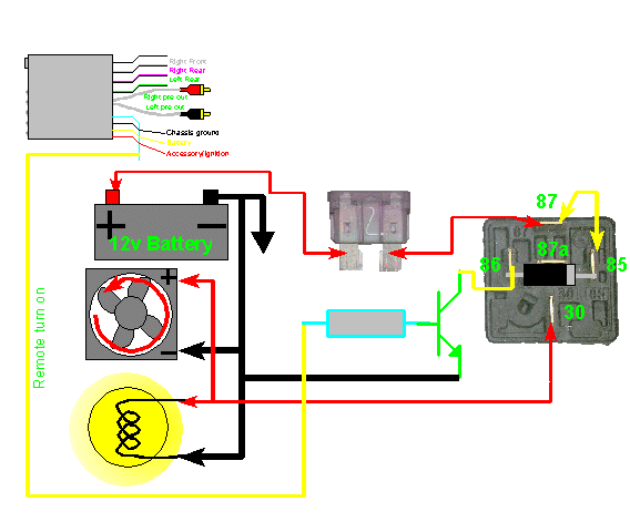
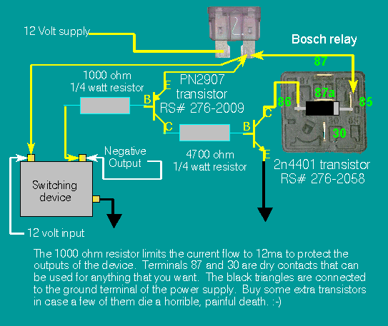
v.1
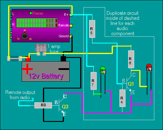
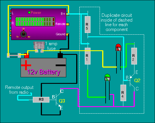
third choice...
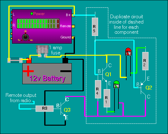
Possible supplier: Radio Shack
Parts list:
Bipolar npn transistor: (Q1 & Q3) 2N4401 RS # 276-2058
Bipolar pnp transistor: (Q2) PN2907 RS # 276-2009
Bipolar npn transistor: (option for Q3) TIP31 RS # 276-2017
Resistors:
R1,R2,R3: 1000 ohms RS # 271-1321
R4: 47000 ohms RS # 271-1342
R5: 4700 ohms RS # 271-1330
R6,R7: 2200 ohms RS # 271-1325
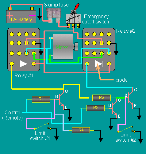
- Neither limit switch grounded:
Motor runs in one of two directions. The direction of ratation is determined by the control voltage. It will not stop running until one or both of the limit switches are connected to ground. - Control high:
Motor runs in direction 'A' until limit switch #1 is connected to ground. The limit switch can actually be anything including a piece of wire with the insulation stripped off of the tip. - Control low:
Motor runs in direction 'B' until the control goes high or the limit switch is connected to ground. - Safety switch will act like a master switch to shut everything off if something goes haywire (technical term).
Possible supplier: Radio Shack
Parts list:
Bipolar npn transistor: (all transistors) 2N4401 RS # 276-2058
Resistors:
R1,R2,R3: 4700 ohms RS # 271-1330
R4: 47000 ohms RS # 271-1342
Relays: 4PDT  RS # 275-214
Relay socket: RS # 275-221
Safety switch: RS # 275-324 (not critical)
Diodes: 1N4003 RS # 276-1102
!2 volt car battery: RS # 275-just kidding